[For the full project details go to the Saund-Box Project Page.]
For my Holiday project I am going to build a low budget modular analog synthesizer as I explain in an earlier post. Here I thought I would spec out exactly what the project entails and the steps involved.
In a nut shell I will be building the full version of the Synth-DIY Experimenter Board (SEB) designed by Ray Wilson of Music From Outer Space (MFOS), but I will be adding the Micro-sample & Hold Module, as well as the “kludge” modifications suggested by Ray himself, and powering the unit with the MFOS Wall Wart Power Supply.
I also want my kids to be able to play with the synth so I’m going to add an internal speaker using the amp circuit from the Noise Toaster project as well as a headphone jack so they don’t have to hook the board up to an amplifier to use it.
Definitely a challenge for me as most of the projects on MFOS, including this one, only provide a PCB board for the build – everything else has to be sourced and built by the user and, as you will see, that can add up to a bit of work.
Ray does provide a front panel template and art for SEB:

with accompanying wiring diagram:

Which would save a lot of time and effort if it wasn’t for the fact that I’m adding the Sample & Hold module and kludge options and want to fit them all onto one panel, preferably of legal page size (8.5″ x 14″) or less so it is easier to print.
So the steps involved in completing the project go something like this:
- Purchase the PCB boards for SEB and the sample & hold module.
- Purchase the wall wart power supply kit (which actually has everything included so that is easy at least)
- Source and purchase all the electronic components and hardware
- Source and purchase aluminum sheet for the front panel
- Design front panel layout, create template and final art
- Create wiring diagram for panel components
- Build the power supply
- Solder in all PCB components for SEB and the Sample & Hold board.
- Create the front panel. Mount the panel components and boards. Wire it all up
- Build an enclosure
- Add the power supply and mount the front panel to the enclosure
- Power up and have fun….hopefully
I’ve already completed the first five parts, though I still have some components left to purchase.
The creation of the panel layout was a major effort and I will dedicate a whole post on how I went about doing that using Inkscape. In the meantime here is a tease of what the panel will look like:

I’m very happy with the layout. Managed to make it all fit within an 8.5″ x 14″ area, although I’m only allowing for 3/8″ around the edge of the panel for mounting to the enclosure.
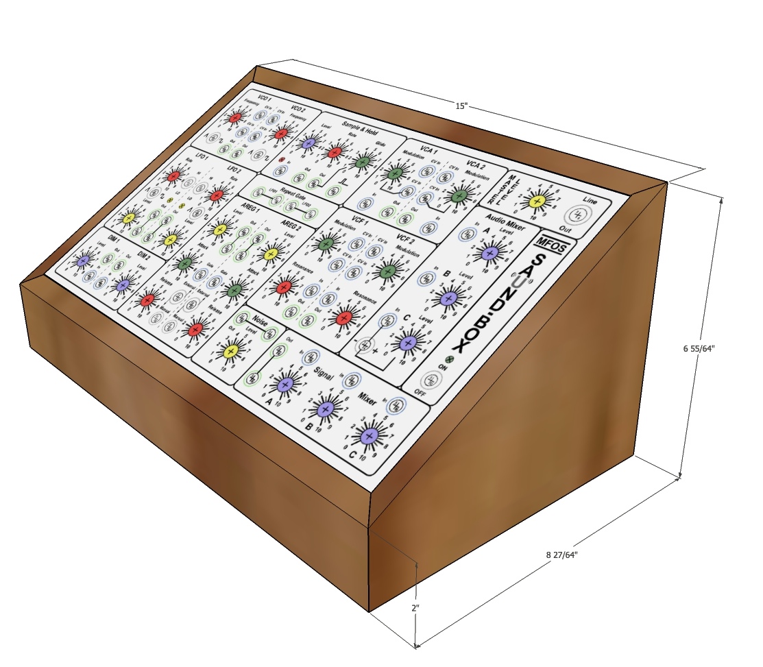
For the enclosure I’m lucky enough to have a friend who is very good at wood work and has the tools to boot. I’ve used SketchUp to design a simple enclose box using 3/4″ fir wood. Here is a render of the front:
And from the rear with the back panel removed:

And finally I though I would show the master component list I compiled from the SEB, Sample & Hold and kludge BOMs from MFOS. It’s quite a bit of stuff:
| Quantity | Item | Value |
|---|---|---|
| 1 | CD4013 Dual D Flip Flop | CD4013 |
| 1 | LM13700 Dual gm OpAmp or sub | LM13700, LM13600 or NJM13600 |
| 1 | LM3900 Quad Norton Op Amp | LM3900 |
| 6 | TL074 Quad Op Amp | TL074 |
| 1 | LF444 Quad Op Amp | LF444 |
| 1 | 2N5457 N Channel JFET | 2N5457 |
| 5 | 2N3904 | 2N3904 |
| 2 | PN4391 NFET | PN4391 |
| 13 | 1N914 Sw. Diode | 1N914 |
| 2 | General Purpose Green LED | LED Gree |
| 1 | General Purpose Red LED | LED Red |
| 5 | Potentiometer Audio Taper | 1M |
| 7 | Audio Taper Potentiometers | 100K |
| 16 | Potentiometer Linear Taper | 100K |
| 3 | Potentiometer Linear Taper | 1M |
| 4 | Resistor 1/4 Watt 5% | 470 Ohms |
| 4 | Resistor 1/4 Watt 5% | 470K |
| 6 | Resistor 1/4 Watt 5% | 47K |
| 3 | Resistor 1/4 Watt 5% | 560K |
| 2 | Resistor 1/4 Watt 5% | 6.2K |
| 2 | Resistor 1/4 Watt 5% | 62K |
| 2 | Resistor 1/4 Watt 5% | 7.5K |
| 1 | Resistor 1/4 Watt 5% | 75K |
| 4 | Resistor 1/4 Watt 5% | 1.5M |
| 2 | Resistor 1/4 Watt 5% | 100 Ohms |
| 49 | Resistor 1/4 Watt 5% | 100K |
| 12 | Resistor 1/4 Watt 5% | 10K |
| 2 | Resistor 1/4 Watt 5% | 10M |
| 3 | Resistor 1/4 Watt 5% | 150K |
| 8 | Resistor 1/4 Watt 5% | 15K |
| 12 | Resistor 1/4 Watt 5% | 1K |
| 2 | Resistor 1/4 Watt 5% | 1M |
| 7 | Resistor 1/4 Watt 5% | 200K |
| 9 | Resistor 1/4 Watt 5% | 20K |
| 6 | Resistor 1/4 Watt 5% | 270K |
| 1 | Resistor 1/4 Watt 5% | 220 ohm |
| 2 | Resistor 1/4 Watt 5% | 2K |
| 2 | Resistor 1/4 Watt 5% | 30K |
| 6 | Resistor 1/4 Watt 5% | 3K |
| 2 | Resistor 1/4 Watt 5% | 3M |
| 5 | Resistor 1/4 Watt 5% | 4.7K |
| 3 | Trim Pot | 10K |
| 2 | Alum. Electrolytic Capacitor | 10uF |
| 2 | Alum. Electrolytic Capacitor | 22uF |
| 11 | Capacitor Alum. Nonpolarized | 1uF |
| 1 | Capacitor Ceramic | .001uF |
| 4 | Capacitor Ceramic | .01uF |
| 26 | Capacitor Ceramic | .1uF |
| 2 | Capacitor Ceramic | .22uF |
| 2 | Capacitor Ceramic | 22pF |
| 6 | Capacitor Ceramic | .0022uF |
| 2 | Capacitor Ceramic | 47pF |
| 2 | Tantalum Capacitor | 4.7uF |
| 1 | Capacitor Polystyrene Radial Leads | .005uF |
| 4 | SPST Switch | SPST |
| 3 | Switch SPDT | SPDT |
| 2 | Switch SPST N.O. Push Button | SPST |
| 1 | Switch DPDT | DPDT |
| 54 | Banana Jacks | 27 Yellow – 27 Blue |
| 31 | Potentiometer Knobs | 9 Blue – 7 Green – 6 Yellow – 9 Red |
| 1 | Jack 1/4″ 2 Terminal |
When I complete the build I’ll create a final list of parts used and cost too. I already have major sticker shock but I’m having a lot of fun with the project so it’s all good.
