[Refer to the Saund-Box Project page for full details on the synth project.]
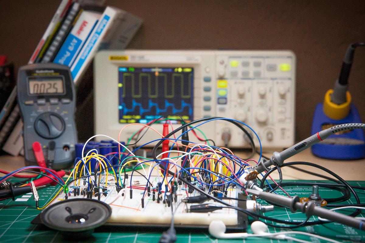
I wanted to add an internal speaker to the synthesizer which meant I was going to have to build an amplifier circuit, and as this was a first for me I decided to breadboard the VCO to use it as a guinea pig.
This turned out to be a great idea for a number of reasons:
- Helped me get familiar the characteristics of the VCO circuit and its components.
- I could verify that the characteristics matched the design specs, which is always reassuring.
- I will be better able to test and trouble shoot the final build.
So after getting the amplifier working with the VCO circuit I decided to breadboard all the modules, and I’m glad I did as the white noise generator and the VCF do benefit from some customization that would be very hard to do directly on the PCB.
In this post I am going to document each of the modules as I build and test them. I will update as I go.
Circuits are powered by +-12V bipolar supply.
Status as of 12/31/14:
| # | Module | max A | min Vpp | max Vpp | min Hz | max Hz |
|---|---|---|---|---|---|---|
| 1 | Amp | 8-180 mA | 0 V | 10 V | — | — |
| 2 | WNG | ~10 mA (*) | N/A | ~10 V | — | — |
| 3 | VCO | ~20 mA (*) | 7.2 V | 8.7 V | ~15 Hz | 4.6 kHz |
| 4 | VCF | ~10 mA (*) | 0 V | — | — | — |
| 5 | VCA | ~20 mA (*) | 0 V | 21 V | — | — |
| 6 | AREG | ~10 mA (*) | 0 V | 10 V | — | — |
| 7 | LFO | ~10 mA (*) | 11.2 V | 13.2 V | 96 mHz | 17.2 kHz |
| 8 | S&H | — | N/A | N/A | — | — |
(*) – Total amperage for both modules
The White Noise Generator
You can find all the details of this module on MFOS: EB White Noise Generator
The white noise generator is a simple enough circuit but definitely recommend breadboarding it first as the transistor at the heart of it, i.e. the 2N3904 or 2N5172, can have a certain amount of variation and you will want to try a few to see which gives the strongest output.
The 2N5172 transistors can be particularly noisy and Ray recommends a 10K resistor for R148. However for the two 2n5172’s I had I needed a value more in the 5K range so I do really recommend building this circuit to a) pick a good transistor and b) choose a resistor for R148 that lets you use the R150 trim pot to adjust the output signal to around 10V peak to peak, like this:
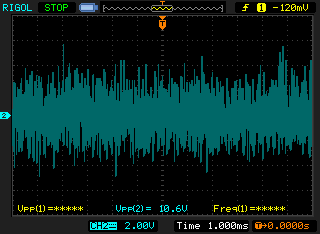
And here it is in action:
The Amplifier
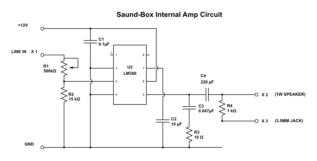
This is the one circuit I had to research and design myself but turns out it’s a piece of cake if you use the LM386. The only real trick dividing down the voltage coming into the amp to avoid overdriving it, and then also dividing down output level to something that headphones can handle.
Working backwards I’m aiming for a typical max output of about 10V which means an input of 500mV. Then the question becomes: “What is the typical max voltage coming into the amp?”.
At this point I’m not sure what the typical voltage range of the modules are. I’ve only built the VCO, VCF and WNG so far, and the WNG has the largest level at 10V peak-to-peak. The other factor to consider is that the Audio Mixer module also doubles the levels of its inputs when turned up to the max.
Therefore I plan to use a trim pot so I can normalize the input level once everything is built.
And here is the circuit schematic:
The VCO
You can find all the details of this module at MFOS:EB Sound Effect Oscillator
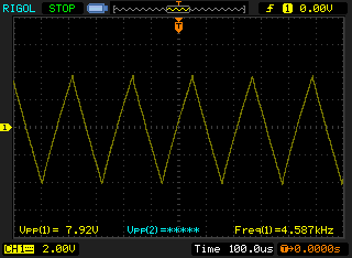
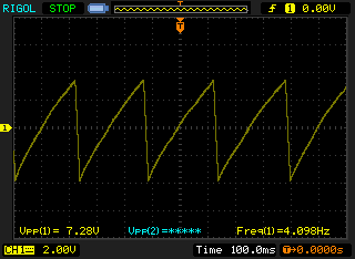
Here are some captures of both waveforms at different frequencies. The highest frequency for both is around 4.6 kHz and lowest is in the 10 to 15 Hz range.
Triangle wave at max frequency:
At very low frequencies it gets a bit lob sided:
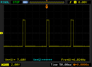
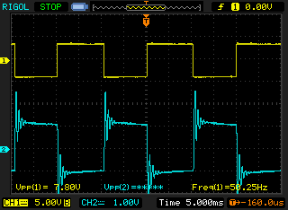
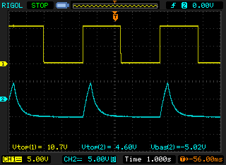
The square wave output at max frequency:

Square waves get more distorted at the lower frequencies:
There is about a 1 Vpp difference between the triangle and square wave outputs.
The output voltage is around 8.7 Vpp at max frequency and 7.2 Vpp at the lowest.
At the very low frequencies you can notice some random drift of a few Hz.
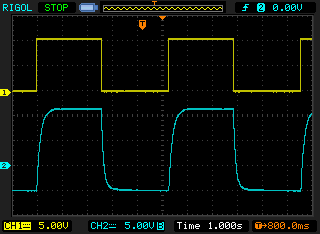
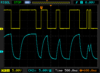
The VCA
You can find all the details of this module at MFOS:EB VCA Module
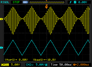
Full modulation using triangle wave from LFO:
Full modulation using square wave from LFO:

Half modulation using square wave from LFO:

The VCF
You can find all the details of this module at MFOS:EB VCF Module
Had a lot of fun playing around with this module on the breadboard.
Very easy to trim this if you have an oscilloscope, though if you are building this project you should really have a scope or access to one.
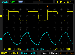
Here are some scope captures at different settings. I mainly used a square wave input as it is the most interesting to see and hear through the VCF.
3 kHz signal with mid point cut-off frequency at full resonance :

No resonance:
At 50 Hz:

With full resonance:
The output levels can vary significantly, though generally it is attenuated.
The LFO
You can find all the details of this module at MFOS:EB LFO
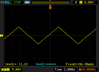
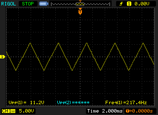
The LFO goes from 96 mHz (10 second cycle) to 217 Hz on the low setting:
On the high setting it goes from 100 Hz to 17.2 kHz:
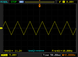
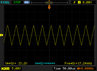
There is no difference between the triangle and square wave output levels.
The output voltage is around 13.2 Vpp at max frequency and 11.2 Vpp at the lowest.
There is no distortion of the wave forms at any frequency.
Sample & Hold
[pending…]
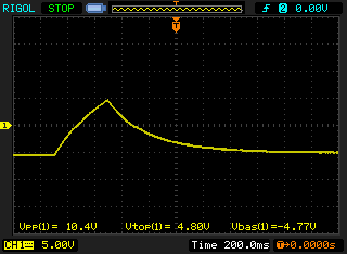
The AREG
You can find all the details of this module at MFOS:EB AREG
Here is a capture of the AREG output for a full attack/release cycle:
In Gate mode using the LFO repeat gate as an external input:
In Gate mode using the manual push button:
In Trigger mode using the LFO gate:
in Trigger mode using the manual push button:

And using the AREG output as an input to the VCA module:

