I’ve been trying to figure out power supply options for my future projects and it’s been surprisingly difficult due to the fact that I need both positive and negative power rails for a lot of the audio based op-amp circuits I’ll be working on.
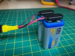
Had thought about going all minimalistic and just using 9V batteries. Even built a harness for that purpose but ultimately decided to standardize on +/-12V rails to be compatible with euro rack in case I wanted to dabble with that format down the road. Also being able to vary the supply seems very useful so out with the minimalistic battery idea and in with a proper power supply – which, as it turns out, is not so easy.
An affordable version of a bipolar power supply I would like to have doesn’t exist if I want to stay below $150 or more preferable under $100. An alternative is to employ two regular bench supplies, i.e. ones that only have +/- terminals, and put them in series but that is not only just as expensive but also cumbersome and takes up too much bench space. In fact most of the bench supplies I looked at were quite large.
However I did come across Elenco’s XP-720 Power Supply in kit form and while it is not ideal it does meet a lot of my needs.
Eh, What is Bipolar?
Typical circuits have a supply voltage that comes from a battery’s (or power supply’s) + and – terminals. Schematically we think of the + terminal as the supply voltage, i.e. VCC or 5V for TTL circuits, and the – terminal as 0 volts or (virtual) ground, i.e. GND. In that type of circuit all voltages are positive relative to virtual ground.
However, there are applications where we want voltages be positive or negative relative to ground. For example, audio circuits where we are using op-ams. In this case we need three terminals from the supply; a positive terminal, a ground/common terminal and a negative terminal.
There are different names used for this kind of setup, such as dual, split, tracking and bipolar.
Elenco’s XP-720 Kit
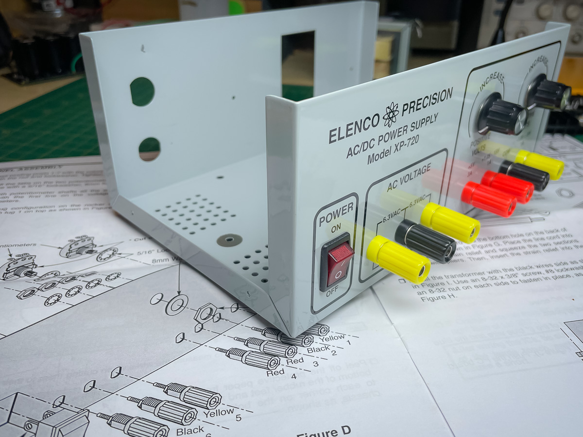
This is what it looks like after assembly:

It definitely is your grandfather’s power supply; weighing 5 3/4 lbs (2.5 Kg) and you can feel the transformer humming when you lay your hand on it. (Thankfully you don’t hear it humming… yet).
It has a fixed +5V output that is rated up to 3A. All the other outputs are rated to 1A. There is a positive and negative output that both range from 1.25V to 20V relative to the “com” terminal, which is virtual ground for all the outputs. There are two AC outputs 180 degrees out of phase so you can use them individually at 6.3VAC or together at 12.6 VAC. The voltage dials (2k ohm potentiometers) are single turn so not the greatest resolution.
Not exactly cheap at $70 when you compare it to the features of the more modern inexpensive units and it has some significant negatives:
- Outputs are individually set manually.
- There is no voltage or current display so have to use a multimeter to be sure of the output.
- There is no current limiting or any other type of safety feature.
- One can easily brush against the dials and change the output by mistake, maybe even damage a circuit.
- For just under twice the price you can get a pretty nice bench supply with all the modern features, though it would not be bipolar.
Still it has its good points:
- It is a linear bipolar adjustable power supply.
- Has the 6/12 VAC outputs which is actually very useful to me.
- Gives hands on experience building and understanding how a basic power supply works.
- Will be easy to modify later and be a project of its own.
- Or can be used as a template for making something more suitable.
- Fits very nicely on the bench
- It’s so retro it’s cool!
- And while it’s not cheap, it isn’t expensive either.
XP-720 Schematic
The manual has a nice schematic that shows how the unit works:
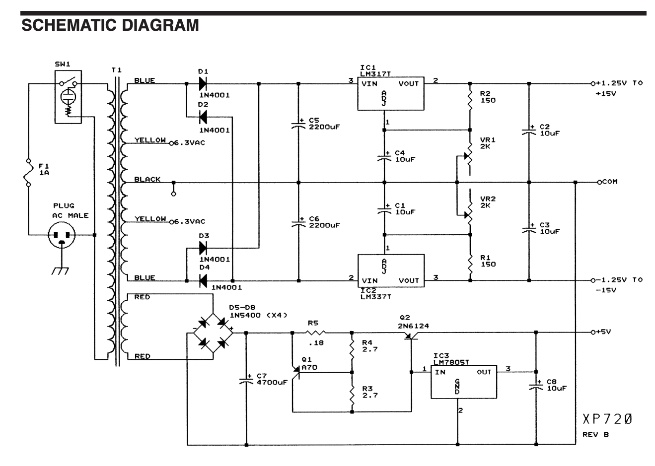
As you can see it’s nothing fancy. A step-down transformer (120VAC to 17VAC), rectified to DC and then feed through some voltage regulators, two of which have adjustable output controlled via potentiometers. Assuming the transformer doesn’t fail it’ll be very easy to repair any future problems.
Building The Kit
The kit comes with everything needed to build the unit. You can checkout the XP-720’s manual online to see how it all goes together. It’s very thorough and easy to follow.
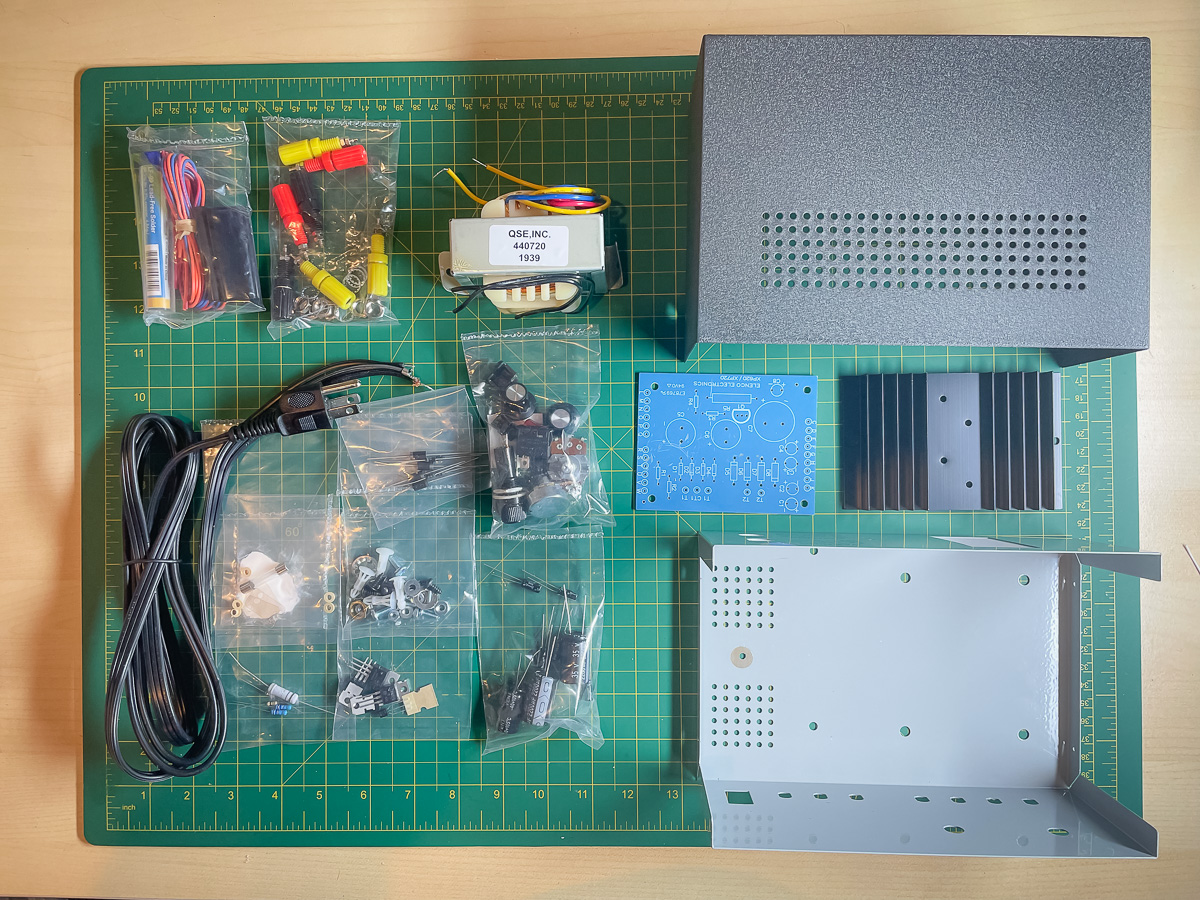
These are the kit’s contents as they come out of the box:
The only issue I had was bent horns on the transformer:
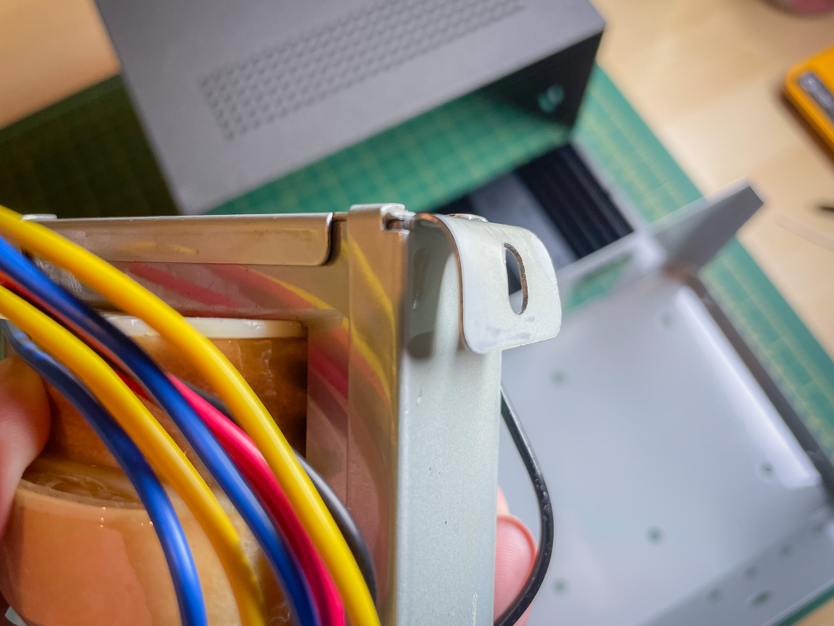
They were easy to straighten and there were no other signs of damage.
First step is installing the front panel components:
Then the rear panel:
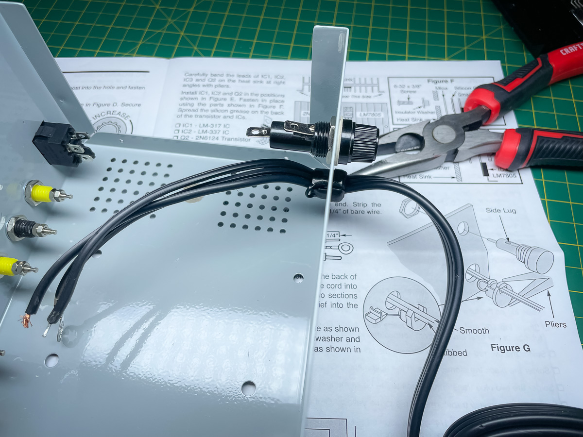
Installing the mains wire was tricky. Need a good set of pliers and make sure to align things up correctly before squeezing the two sections of the strain relief together.
Next was installing the transformer:
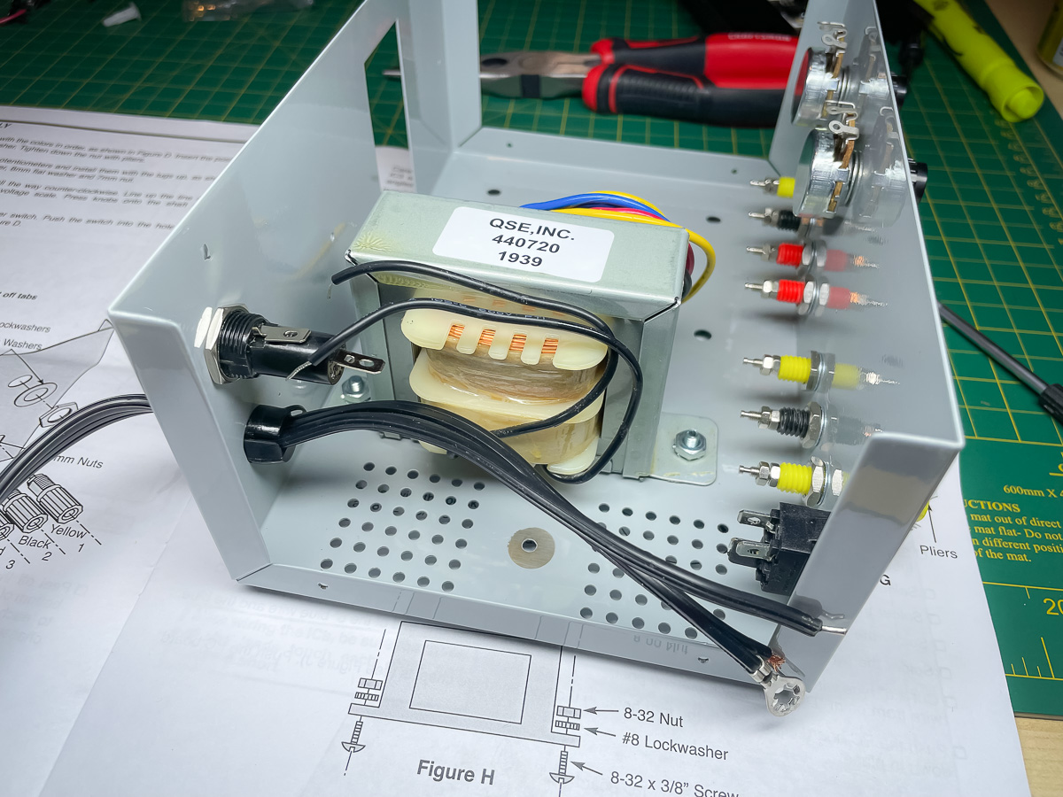
Then wiring up the mains to the fuse, transformer and power switch:

Only issue here was the heat shrink tubing for the power switch not fitting over the switch casing.
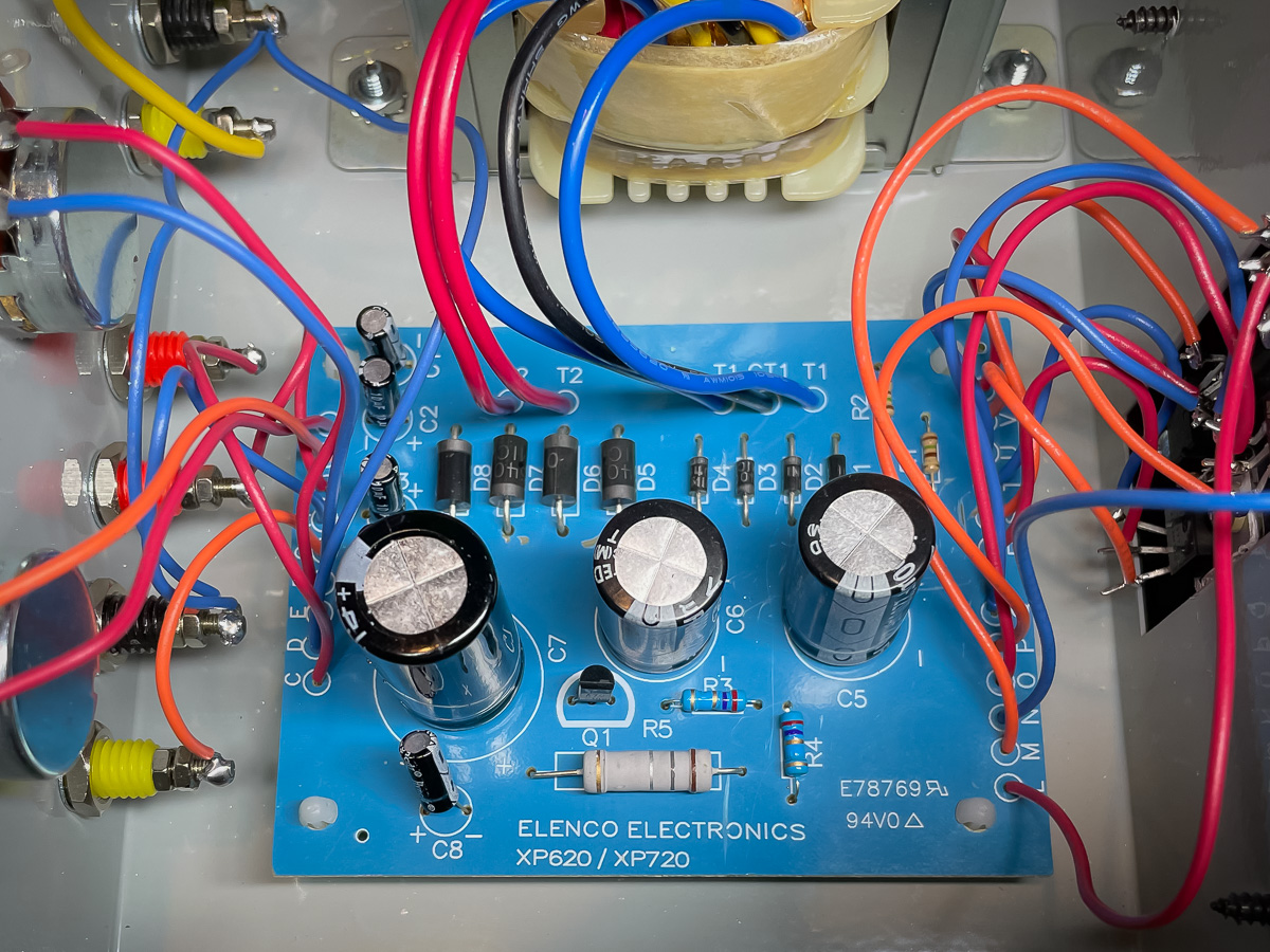
Forgot to take images of assembling the PCB but here is the underside after completion:
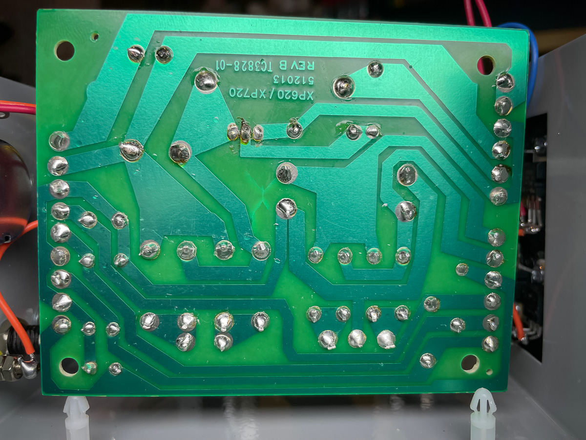
Soldering the components to the board was a challenge. They recommend to only use the tin based solder that comes with the kit. However you need a higher tip temperature for this type of solder – I set mine to 710F – and with the large pads and traces it is very hard to get it to flow well. On top of that I managed to install the A70 transistor (Q1) backwards so had to de-solder and re-solder it. Ugh! If you are new to soldering I definitely recommend getting more experience on other basic kits before attempting this one. You want to have solid connections here.
Also note that there are a lot wires with specific lengths that need to be soldered to the PCB. It’s fiddly work and super easy to mess up which wire goes where so take your time and be methodical.
Next was attaching the regulators to the heat sink. Again pay attention to how these are attached, particularly the LM7805 (IC3) as you don’t want any part of it connecting to the metal of the heat sink.
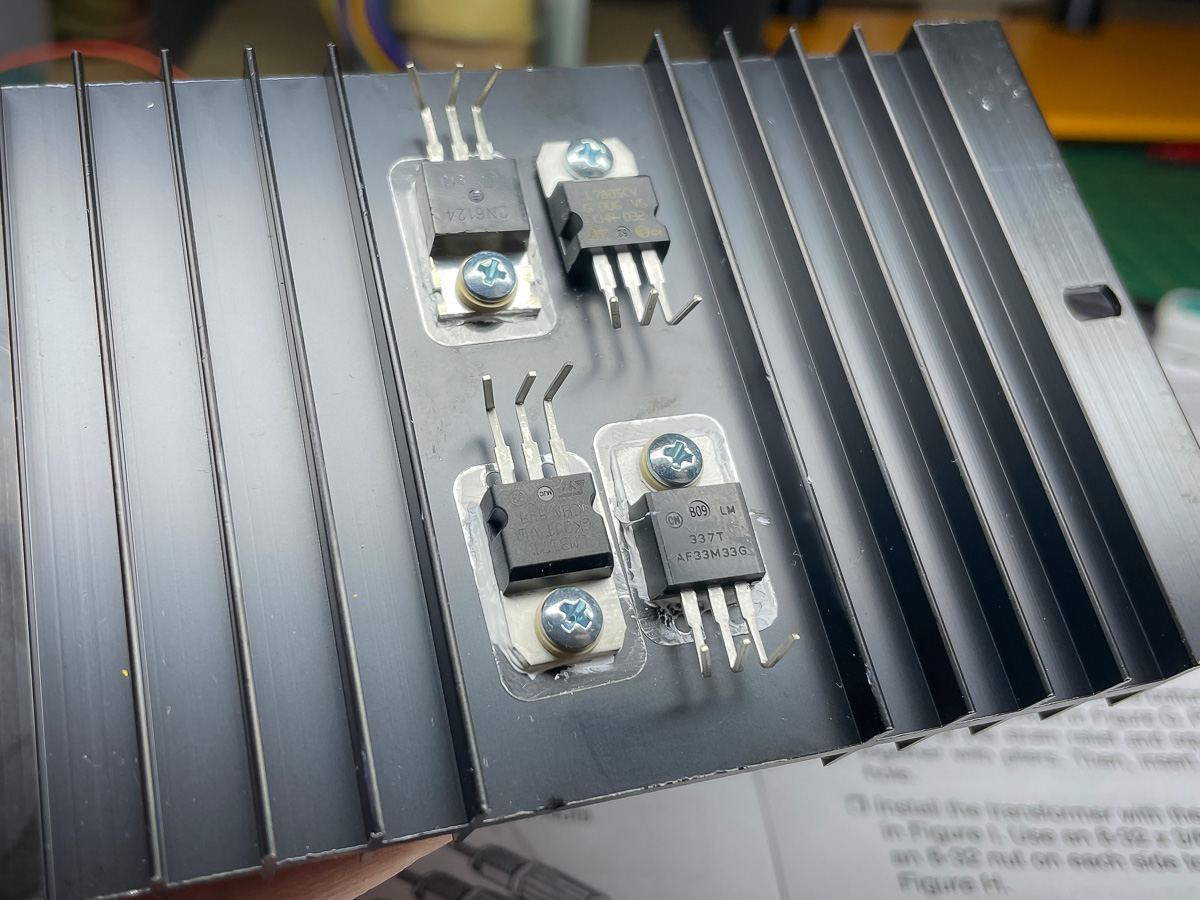
Also note (in the following image) that I had to modify how I initially bent the pins on the 2N6124 and the LM337 so they don’t connect with the chasis.

Next was wiring up the regulators:
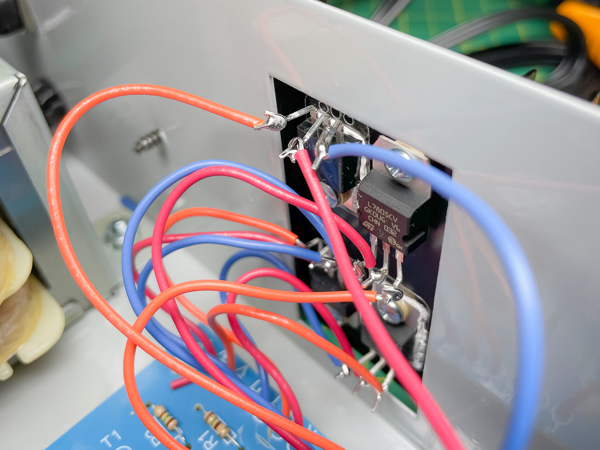
This was another tricky part of the build. I have to say it looks pretty sketchy to me to see so much bare metal. In hindsight I would do this a little differently by soldering the wires on in-line with the pins and using heat shrink to totally cover them.
By the way, I used lead solder for everything that wasn’t on the PCB.
Here is a view of the front panel wiring:

Wiring the front panel was slightly challenging in that you have to be careful getting the iron in to certain places to avoid burning existing wires.
Here is a shot of the PCB in situ, all wired up.
One thing you’ll notice with the heat sink is that the regulators (and their bare pins) are partially exposed to the outside via gaps in the top and bottom of the sink. To help prevent foreign bodies falling in and short-circuiting something, I added electrical tape over the gaps:
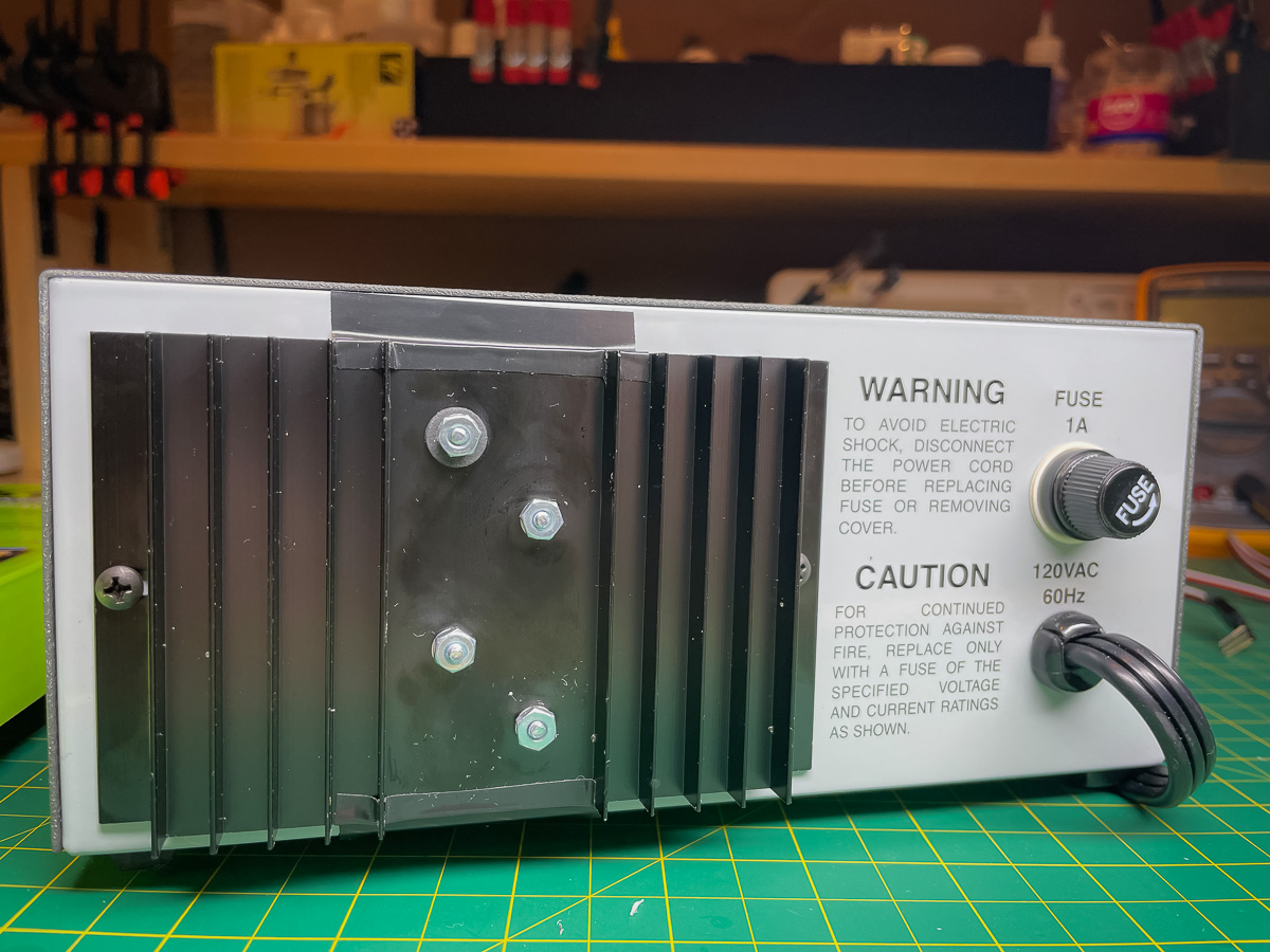
A bit ghetto but does the trick.
Finally powered up the unit and everything worked perfectly. Ordered some power resistors so I can test it under load. Most curious to see how much ripple/noise there is. Will append this post or create a new one when I have some test results.
In the meantime it’s setup in my workspace and fits like a glove:
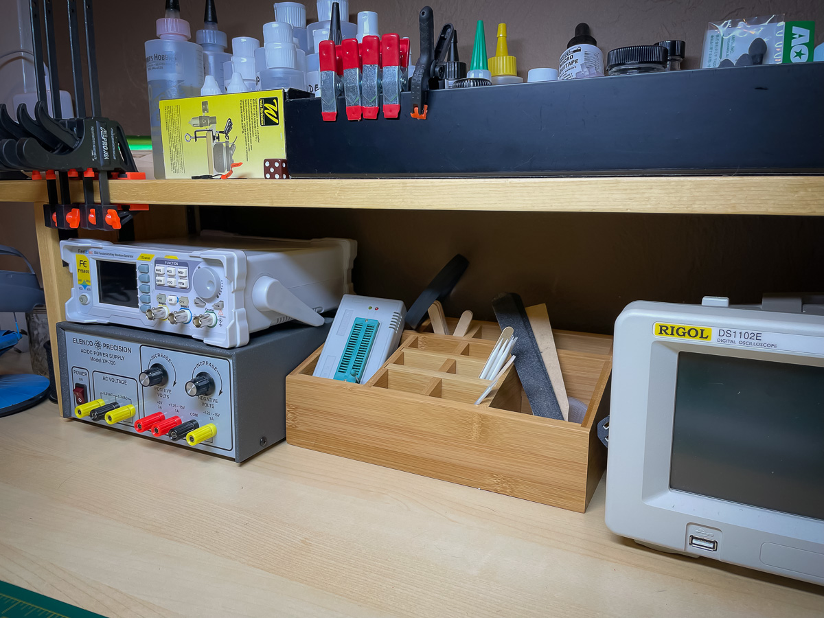
Time will tell if this was a good purchase. Already plan to swap out the single turn potentiometers with 10 turn ones, partially for better accuracy but mainly to minimize damage from unintentional turns of the dials. Rather than a possible 19 volt jump, worst case, it’ll be limited to just under 2 volts at max.

Did you ever get to testing this PSU?
LikeLike
Hi Jason,
Yes I did. You can read about it here: https://solderspot.net/2021/11/13/xp-720-simple-load-test/
LikeLike
Thanks for the update!
I just got an Elenco XP800. It was a salvage sale so a total gamble at $25 plus shipping. Powers up but nothing more tested. I need to test it further. I want to use it to
Power some low voltage, higher current drivers. My Heath Kit PSU powers my other FC drivers but they are 3000VDC coils as opposed to the 12VDC coil drivers I recently got. Maybe ne has a variable 0-120V AC tap on the back which is useful for old audio gear. Thanks for documenting all of your work. Regards, Jason (polkiju7 on YouTube BTW)
LikeLike