
Saund-Box Project
In this project I built a noise-effects synthesizer using Ray Wilson’s Music From Outer Space Synth-DIY Experimenter Board and Micro Sample & Hold module, and the Wall Wart Power Supply Kit.
It includes 2 voltage controlled oscillators (VCO), 2 low-frequency oscillators (LFO), 2 voltage controlled low-pass filters (VCF), 2 voltage controlled amplifiers (VCA), 2 attack/release envelope generators (AREG), the sample & hold module, a white noise generator and 2 signal mixers.
All control voltages have linear responses and can drift. This is not a synthesizer you can use as an instrument. It is meant for creating cool sounds.
Module inputs and outputs are configured using patch cords via banana jacks.
Design Files
You can obtain all the design files I created for this project in the Saund-Box-Files repo on GitHub.
Very Sad News
Ray Wilson, the designer of this synth and all the amazing work on his MFOS site, had been battling cancer for many many month but tragically succumbed to the disease last week (21 July 2016). A huge loss for the DIY community and, of course, his family.
Status: Completed
The synth is fully built. I still need to do a post mortem as I get familiar with its operation.
Project completed: 1/21/15:
| # | Task | Status |
|---|---|---|
| 1 | Purchase boards | ✓ |
| 2 | Source and purchase components | ✓ |
| 3 | Design front panel and template | ✓ |
| 4 | Create panel wiring diagram | ✓ |
| 5 | Design enclosure | ✓ |
| 6 | Design amplifier for internal speaker and headphones | ✓ |
| 7 | Build power supply | ✓ |
| 8 | Build amplifier circuit | ✓ |
| 9 | Pre-testing the circuits | ✓ |
| 10 | Populate boards | ✓ |
| 11 | Build front panel | ✓ |
| 12 | Build enclosure | ✓ |
| 13 | Mount panel components | ✓ |
| 14 | Wire up panel components | ✓ |
| 15 | Install boards and wire them up to panel components | ✓ |
| 16 | Test and debug all circuits | ✓ |
| 17 | Mount electronics onto enclosure | ✓ |
| 18 | Rock out! | in-progress |
Starting Point
The starting point for the project was…
The Synth-DIY Experimenter PCB
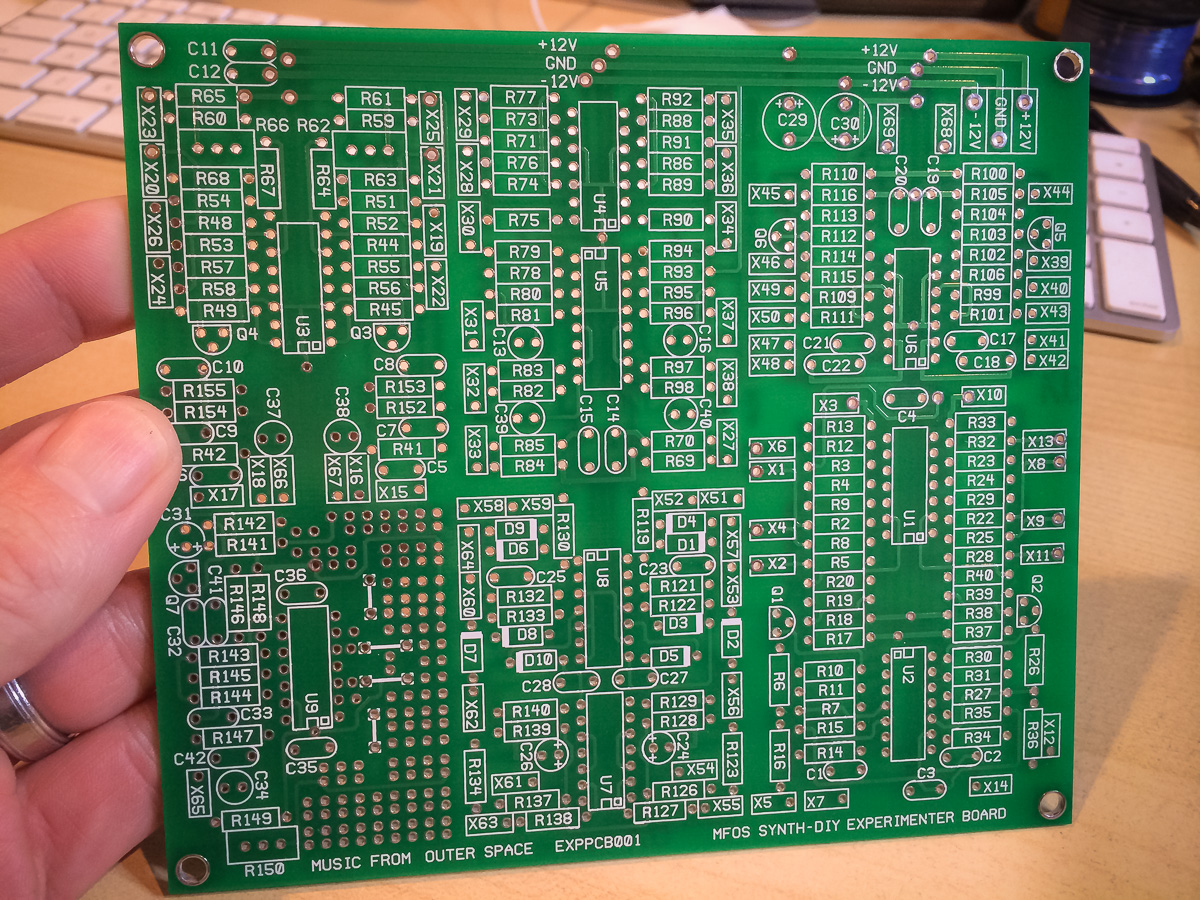
purchased from the MFOS site.
Everything else needs to be sourced, bought and assembled on your own. The MFOS site provides all the information needed, like BOMs and schematics, plus lots of great advice and ideas. Nevertheless it is not a simple project to undertake.
If you were feeling particularly adventurous you could build the PC boards yourself.
Power Supply Unit
It is possible to power the synth with batteries but I opted to use MFOS’s wall wart based power rectifier. Unlike almost every other project on MFOS, this unit can be bought as a complete kit and is super easy to assemble:
Before

After
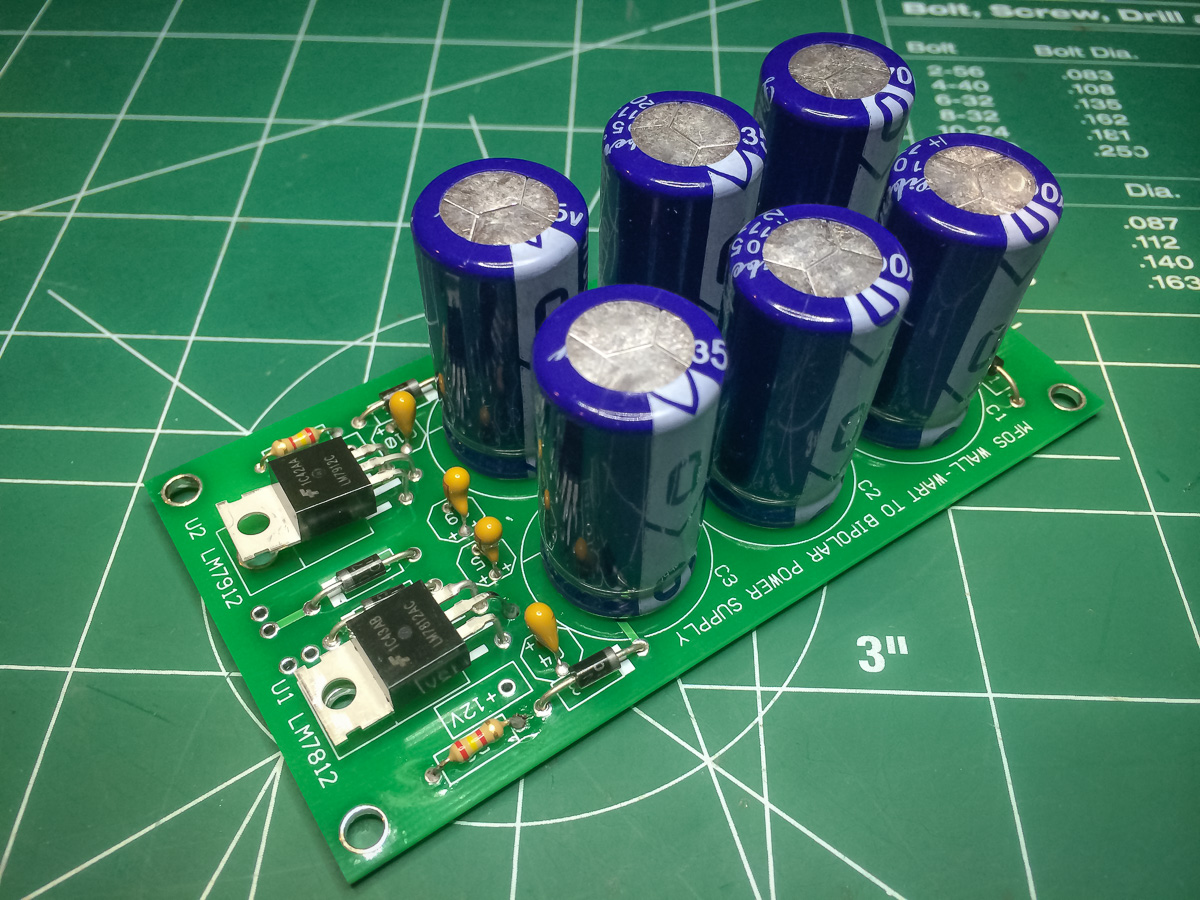
I selected the +/- 12V version and it works like a dream. No noise shows up on the oscilloscope.
Checkout the main page on MFOS for all the details: Wall Wart Power Supply.
My Modifications
I built the synth pretty much as Ray designed it.
My main mod is more of an addition than anything else as I wanted my family to be able to use the synth without having to hook it up to a stereo or computer, so I’ve added an internal speaker and headphone jack using the following amplifier circuit:
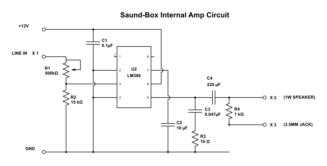
Which I implemented on a perfboard:

I also added a switch to the front panel to turn the speaker on and off. I had hoped to have the headphone jack disconnect the speaker when headphones are plugged in but in the end settled for the switch.


The other mod is very minor. I’ve added a switch to inputs A and B of the signal mixer so they can toggle between DC and AC coupled. The idea is to allow for very low-frequency signals to be mixed. Not sure if this a worthwhile mod but I’d rather have it than not.
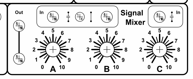
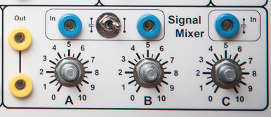
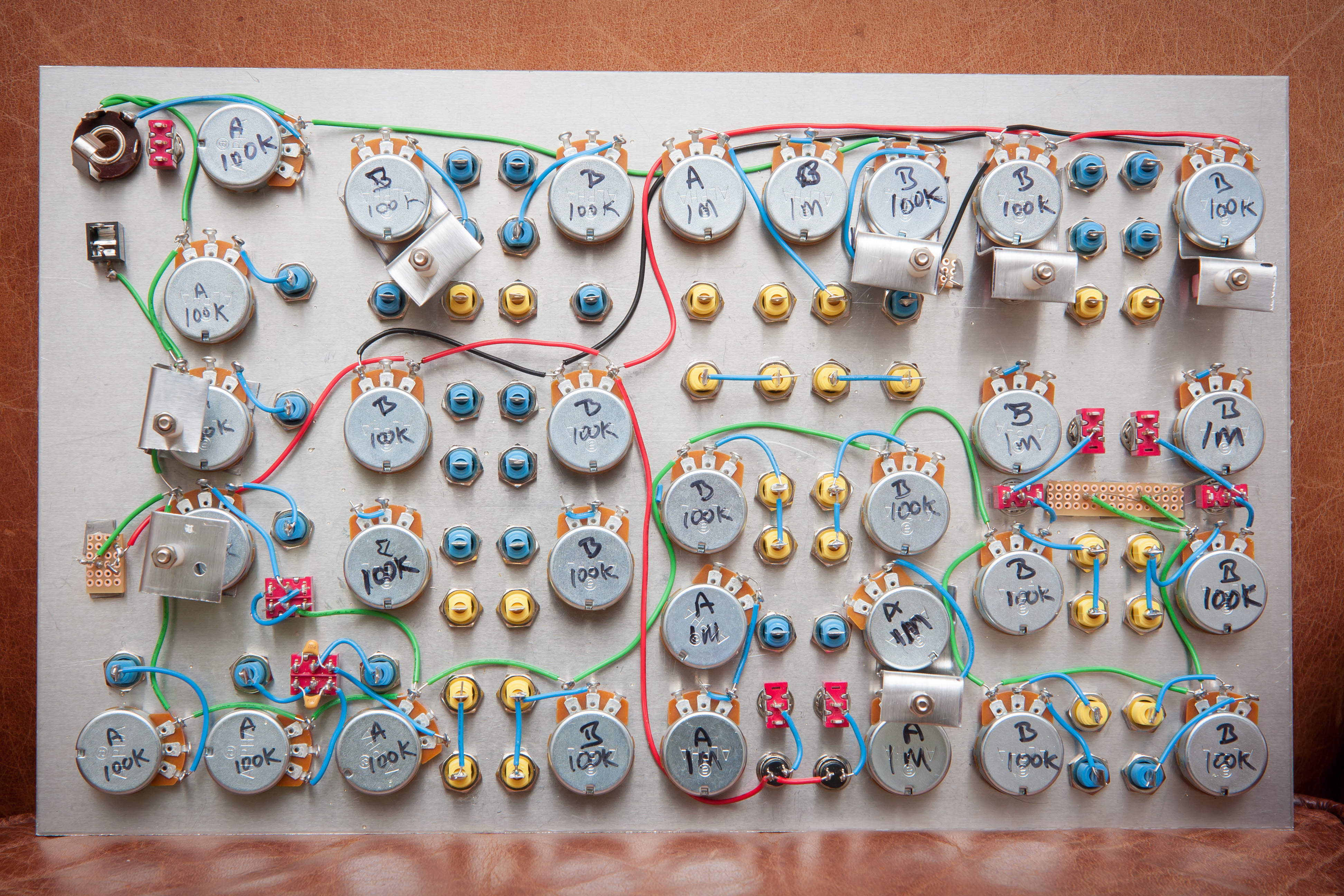
I did want a switch for each input but there was not enough real estate to manage that aesthetically so I compromised by using one DPDT switch for inputs A and B. This also means that the capacitors from A and B have been moved from the kludge area of the main board onto the switch itself, as show in the wiring diagram.

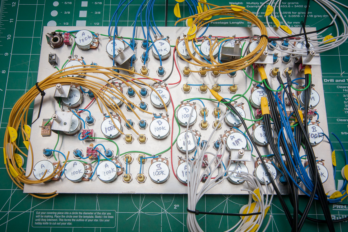
And as you can see here in the actual wiring:

However, I now realize that I didn’t remove the output capacitor so the mod is not complete.
Pre-testing the Circuits
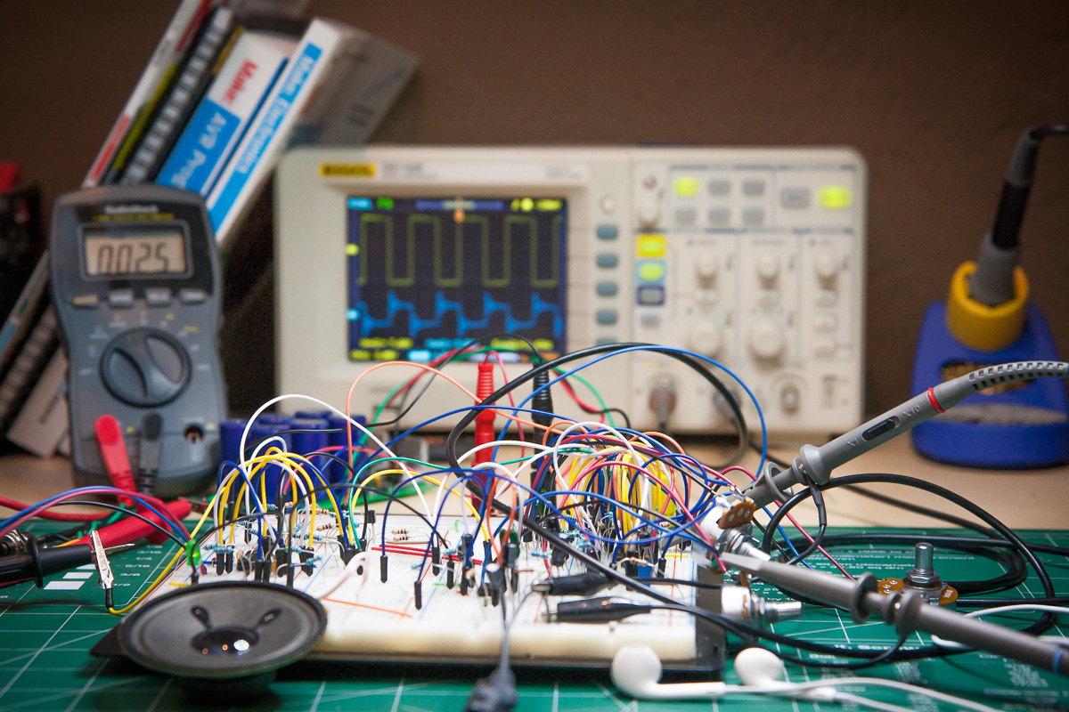
Because I was adding an amplifier circuit, and it was something I hadn’t done before, I assembled the VCO and amplifier circuits on a breadboard in order to experiment with the amp design, particularly with regards to driving headphones.
In the end I breadboarded all the modules, except for Sample & Hold, and I’m mighty glad for it. If you are a newbie, like myself, then I highly recommend doing the same. It is a great way to really get to know the modules, which is invaluable both while building the synth and when it comes time to trouble shoot problems.
In fact, even if you are not a newbie I strongly recommend breadboarding the white noise generator (WNG) and the VCF modules as the transistors you use for them can have an impact on their performance, particularly the WNG.
In my case, for the WNG, the noisiest 2N5172 I had on hand required an R148 resistor value of around 5K Ohms in order to get the trim pot R150 in to the 10 Vpp range. The recommend 10K value would have been too much.
Of course the other benefit of breadboarding is that you get to play with the synth sooner.
I ended up writing a separate post about pre-testing the modules.
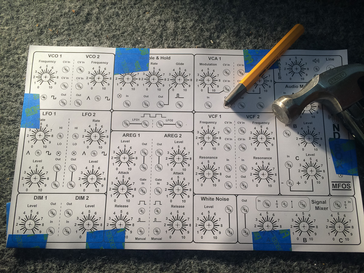
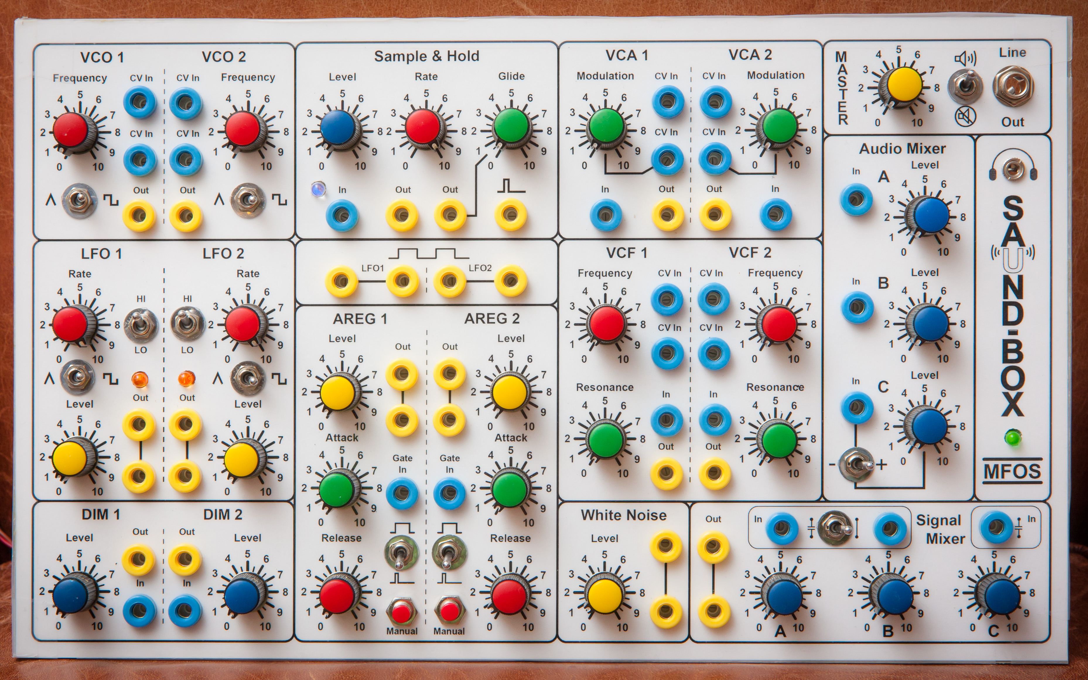
Synth Control Panel Design
Like everything else in this project the synth control panel too needs to be built . Again I’m following Ray’s suggestion on how to create panels using aluminum sheet metal, drill press, laminated paper and glue. To make life easier (and keep the synth as compact as possible) I chose to use a legal (8.5″ x 14″) sized format and thankfully I was able to get all the controls to fit on.
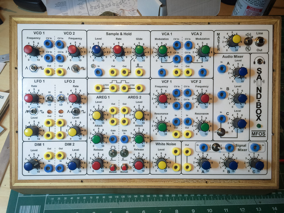
Final panel design:

This was the version used in the build.
You can read about how it was created using Inkscape here.
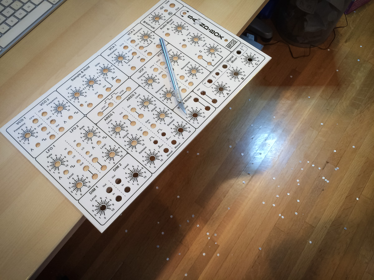
Here is a shot of the panel with most of the components installed:

Wiring Diagram
Final wiring plan:

You can read about how it was created using Inkscape here.
I didn’t detail out the amplifier wiring in the plan as I didn’t want to create artwork for the line out and headphone jacks but here is a view of the final wiring showing exactly how they were hooked up:

For certain wiring I used RCA cable to provide some shielding. These connects are shown in the wiring diagram using thick black lines. To minimize then number of ground wires I daisy chained the cables together like this:
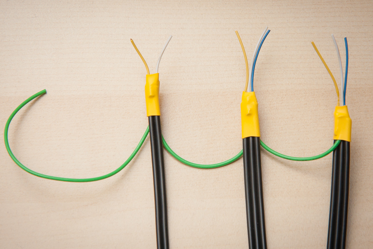
For the LFO and VCO connections I did the grounding at the panel side but for the mixer connections the grounding was done on the board. The reason for this is that I hadn’t accounted for the cable grounding in the wiring plan for the panel and the kludge area had a bunch of ground pads that were much more convenient.
Building the Front Panel
For the front panel build I followed Ray’s method precisely.
As the panel was so large, and I knew the banana jacks can require quite a bit of force, I chose an aluminum sheet thickness of 0.08″ – Ray recommends 0.06″ – and am very happy with it. Still easy to drill and quite a bit sturdier.
Here are some pictures of the process.
Used the panel template printout and center punch to mark the holes to be drilled… and there were a lot of them.
With a very cheap ($70) drill press I first drilled pilot holes. Unfortunately the drill press had some play in it so getting precise hole positions was hard but overall it worked out well.

Then with the correct drill bits drilled the holes proper. With WD40 and a wood block as backing I was able to get virtually no burring.

Did the lamination of the panel legend at a local FedEx store where they also had a superb cutter so was very pleased with the result there too.
Glueing the laminated sheet onto the panel was nerve-racking. Used some tape on one side to help with positioning.

Then applied the contact cement onto the metal surface (not shown).

The major problem I had with the glue was its relatively fast drying time and with the large panel size meant it took quite a bit of time to cover the whole surface. In fact I didn’t get to cover the panel as well as I wanted to. In hindsight I should have used a large foam brush to get the better coverage in a shorter span of time.
When applying the laminated sheet to the metal surface I used a backlight to better position the panel legend over the wholes, luckily the glue hadn’t dried out too much.

After that I burnished the laminated sheet and then placed the panel on a hard flat surface between two sheets of aluminum foil and stacked a buck of heavy books on top for a few hours.
Finally, used an X-Acto knife to cut out the holes. That was some job.
I also ended up taping the edges of the panel to protect it from damage while mounting components, wiring and such, as the lamination can come away from the paper, particularly at the corners.
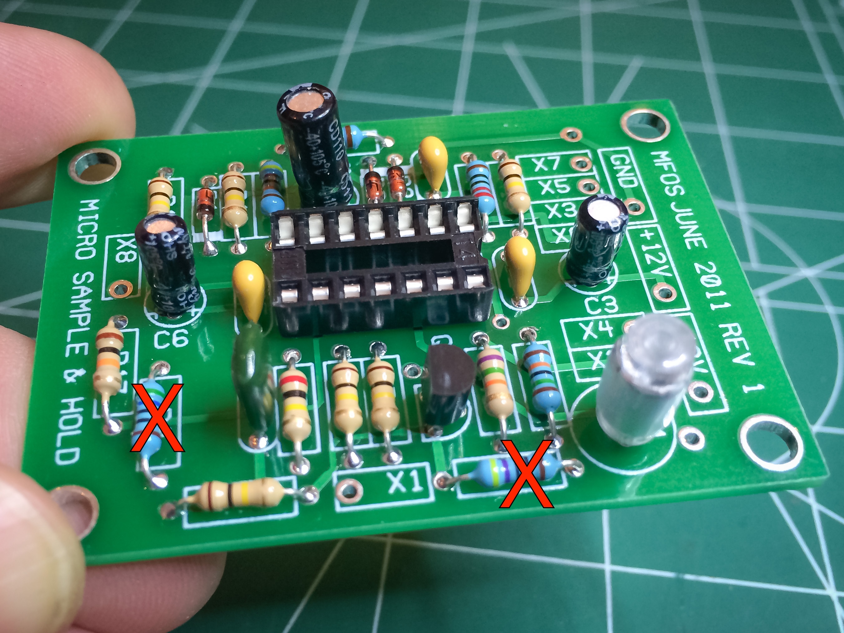
Populating the Boards
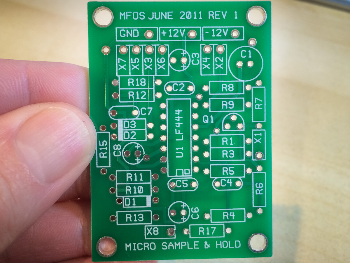
I first started with the Sample & Hold PCB. Ended up getting two resistors wrong (the red X’s in the photo).
Then did the main board.

Did make one error on this board too. Didn’t realize there was meant to be a jumper wire where the red X is but it was a simple enough fix.
The other things to note are: A) I used a 2N5172 transistor for the white noise generator which has different pinouts from the 2N3904 which the board is designed for, so pay attention to that if you do the same, B) I had to replace the 1K Ohm R148 resistor with a 4.7K one, and C) the AC coupling capacitors for signal mixer inputs A and B were moved to the panel as part of a mod I did.
All the PCB Ray provides are of exceptional quality. Very impressed.
Mounting Panel Components and Wiring
Mounting the components was easy enough, except for the LEDs where I took Ray’s suggestion of using perfboard and double-sided foam tape. I think in future I would rather use LED holders if I can find ones with the right aesthetic.
The hardest task for me was mounting the PCBs. First working out where the boards should go and then making the stand-offs. I don’t have any good tools for metal working so it was definitely a slog and not pretty.
Once the board mounting was sorted out I could lockdown all the components and do the initial intra-panel wiring using the wiring plan shown in the section further up.
Used 22AWG solid core wire for all the intra-panel connections. Much easier to work with and shape. Didn’t solder any connections that required wiring up to the boards.
Here is a shot of the panel with the boards mounted:

Next was to wire up the panel components to the boards by first soldering the panel side and label each wire with its X designation. For this I used stranded 20AWG wire as I happen to have a lot of that wire on hand. 22AWG wire would be easier to work with for the hole sizes on the boards. Using different colors between modules made the wiring process a little easier.
My biggest gripe had to do with the labels. They would become unstuck and fall off or stick to another wire. Very annoying. The only upside was that it forced me to keep rechecking the wiring.

Next up I soldered the VCO and LFO RCA (shielded) cables to the panel. Using shielded cables is definitely quite a bit more work but I think it’s worth it. I have noticed some very mild crosstalk between the VCOs but have not looked into the case yet. Most likely I need to add shielded cable for the pot wires but it’s definitely a nit-pick at this point.
There is more serious crosstalk between the CVF modules, and probably the VCA too. I would recommend shielding the signal inputs and outputs for both.
After that it was time to mount the boards and solder the panel wires to their correct destinations. Definite learning curve here with regards to routing the wires, leaving enough slack – so boards can be unmounted and moved about around during troubleshooting – and what order to solder each wire to the board into order to maximize ease of access with the soldering iron.

Next was to solder on the mixer shielded cables. Normally I would have soldered the mixer cables to the panel first, like I did the VCO and LFO ones, but as I didn’t properly plan for the shielded wires it was easier to ground the mixer cables at the board rather than the panel, hence the reverse way of doing these ones.
Finally added the amplifier circuit, speaker and power cables.
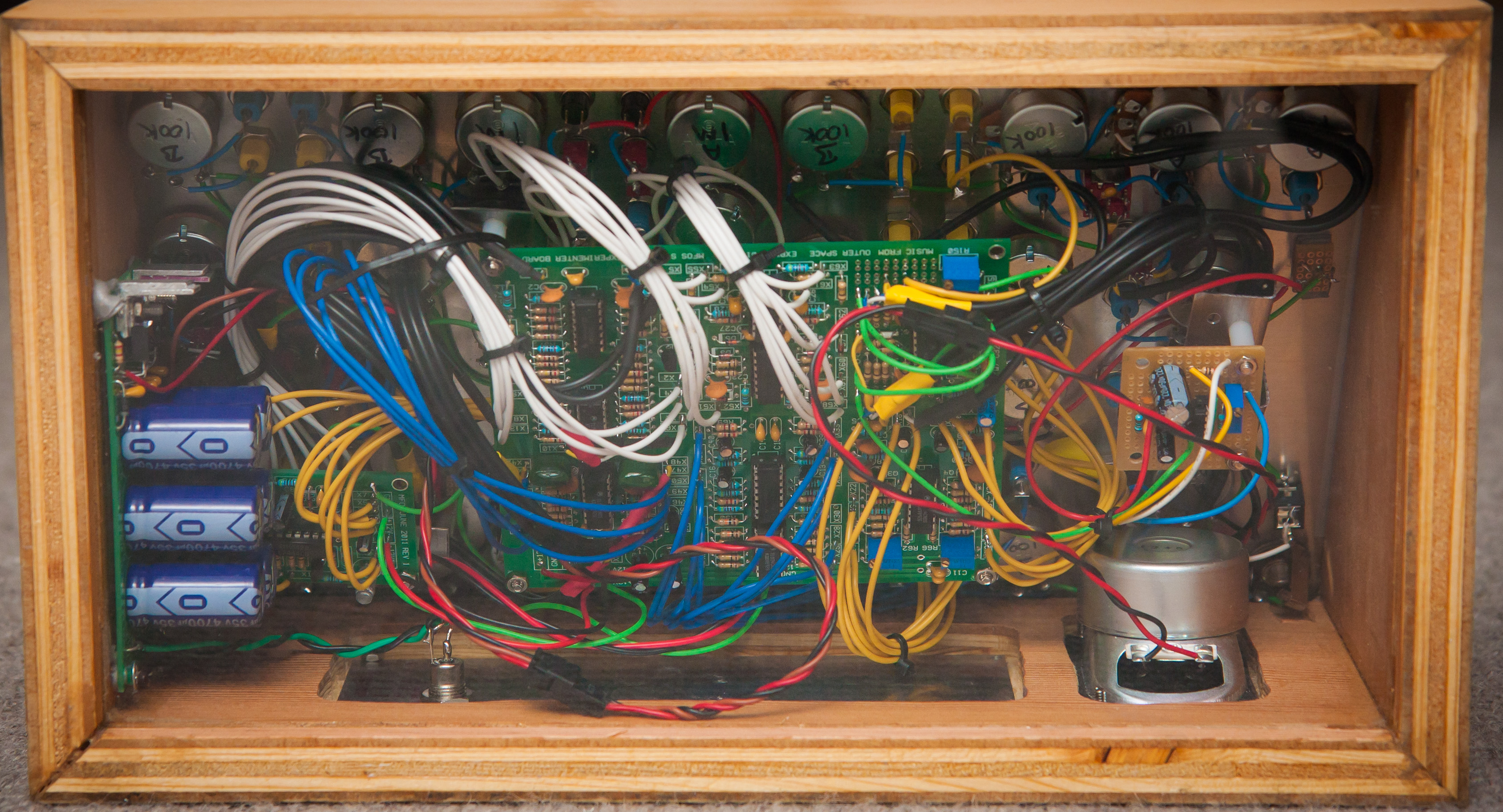
And here is a photo of the final assembly:

And from the front:
Testing and Debugging
My heart was definitely in my mouth when I first powered up the synth. I envisioned smoke billowing out from different components but thankfully there were no sparks, pops or smoke.
However, there were some problems.
Sample & Hold
The Sample & Hold module had a blinking LED but no output. After debugging the board I discovered I had two resistors, R7 and R4, incorrectly placed. Instead of using the required values of 470K and 560K, I had used 470 and 560 Ohm ones. Still, it was easy enough to fix except that while performing the fix I hadn’t powered off the synth and in the process kill the module’s front panel LED. That was a big pain to replace.
VCF
Initially thought that both VCFs were kaput but eventually figured out I had to keep cranking on the trim pots till they go into the correct range.
AREG 2
There was no output for AREG 2. Found that the top banana jack had a cold solder joint. Reflowing the joint promptly fixed that problem.
Signal Mixer
There was also no output from the signal mixer. Eventually realized that I was missing a jump wire from the kludge section. Adding the jump wire was simple enough, though a little tight for space.
MIX 3 & 4
Finally, discovered that the wires for MIX 3 and MIX 4 swapped but, again, a simple enough fix.
Have to say that apart from the busted LED I was very lucky with having such simple problems.
At present I don’t have the final enclosure built so I put together a very crude one for the interim:
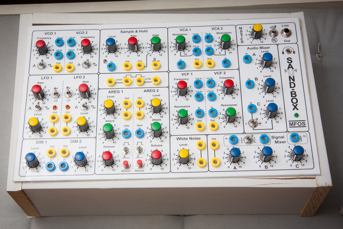
Not pretty but it works.
Testing the Output Quality
I was very curious about what the audio output quality of the synth would be so I did a simple test of hooking up to my PC and recording with Audacity. Here is a screen shot of the captured waveforms for the VCO’s triangle and square wave outputs:
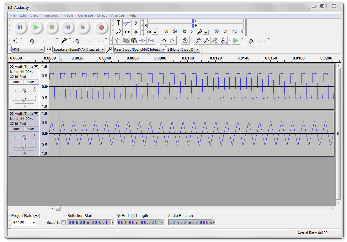
Very impressive.
Here is a short example of the synth in action:
I’ll try to come up with some better examples once I’ve spent more time learning the synth.
[The kind of fizz-pop you’ll notice at the end of the sample is caused when the power is disconnected from the synth. Instead of the synth turning off abruptly, the smoothing capacitors in the rectifier circuit slowly discharge and so the power-down takes a few seconds, causing the synth circuits to go a little cuckoo in the process. Fun.]
So far I’ve not experienced any cross-talk between the wiring so I really can’t be any happier about the performance of the synth.
I have noticed crosstalk between the VCF modules, and very slight crosstalk between the VCOs.
Over the next few days and weeks I’m going to analyze each module in more detail. There were a few minor anomalies that showed up when I pre-tested the circuits on a breadboard. I’m curious to see if there still exist in the final build.
Designing the Enclosure
I’ve only recently discovered SketchUp and it is by far one of my favorite tools now. Surprisingly easy to use and I just love being able to figure out how something is going to come together before building it.
For Saund-Box I kept it simple: a box with the panel at a 30 ° angle from the horizontal.
Decided to use a plexiglass base so that the innards could be visible and placed the power rectifier onto the side of the box so it is more visible from underneath. Probably not optimal for the rectifier.
Here are some renderings from SketchUp.
Side plan view:

You will notice that the master volume pot will protrude into the back panel slightly but it will be easy enough to work around that.
Plan view from the back of the case:

I had hoped to place the speaker on the side panel but it would have been too tight a fit with the amplifier board. Having the speaker on the back panel is not so bad either.
Back panel view:
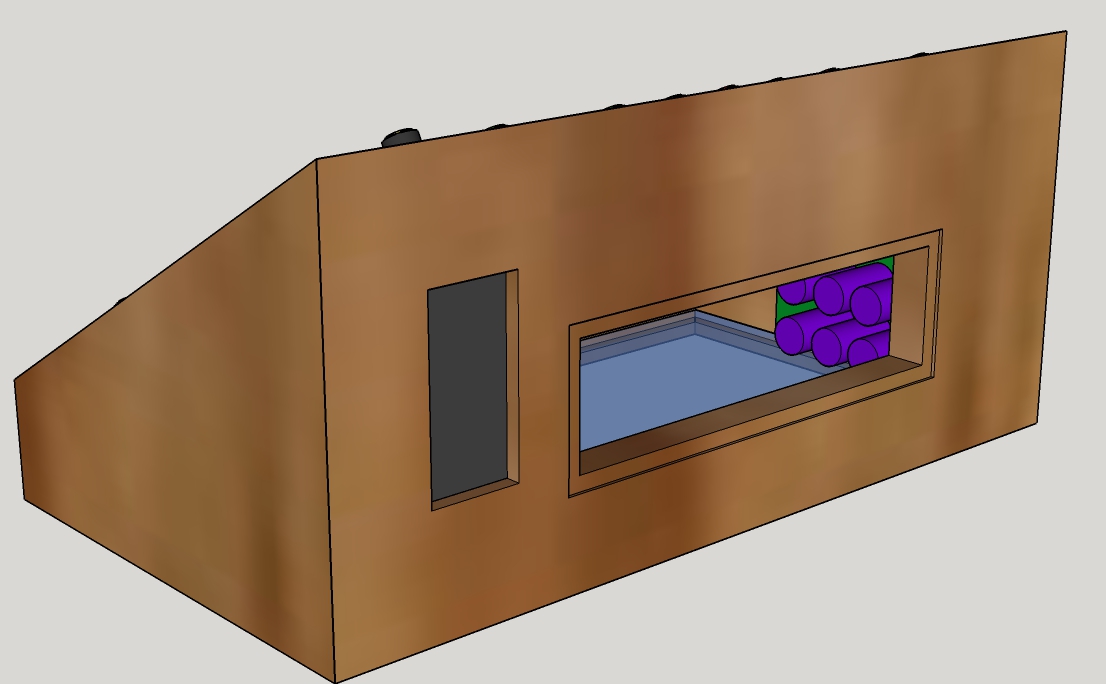
There is a cut out for the speaker and one for a back panel where I can mount the power jack and various other inputs and outputs.
3D view of the innards:
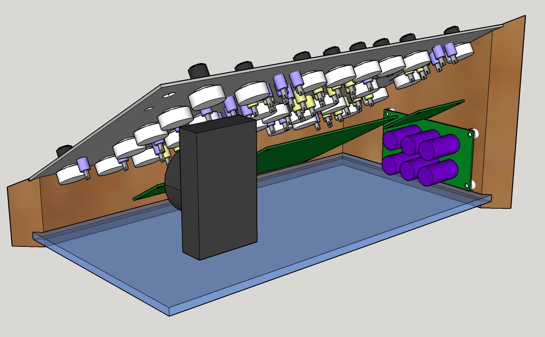
And finally a view of the case with its lid:

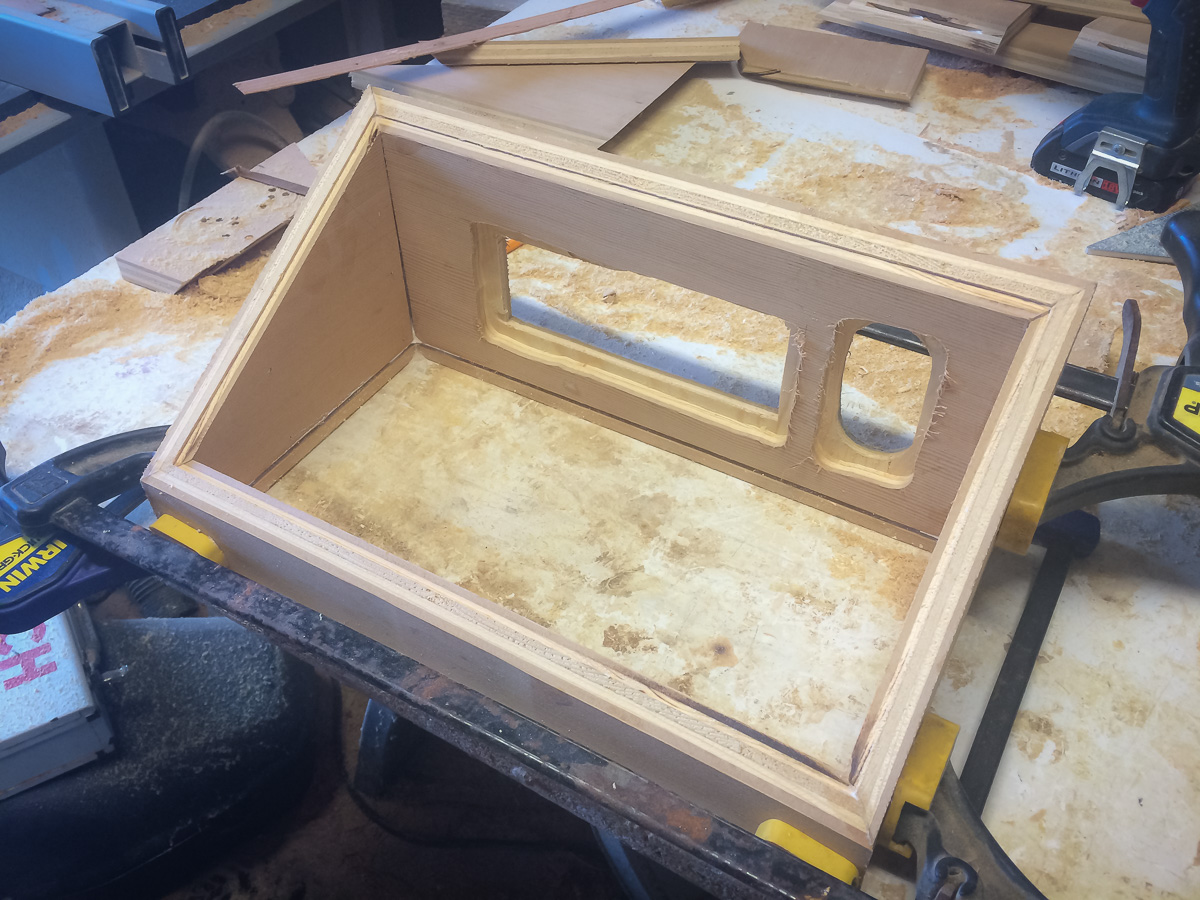
The Enclosure
Luckily I have a friend who has all the woodworking tools and know-how.
I thought the design was simple but with all the angles it was quite a bit of work.
Didn’t take any photos of the build except this one where the base is being glued together:
Eventually mounted the power supply, speaker and back panel:
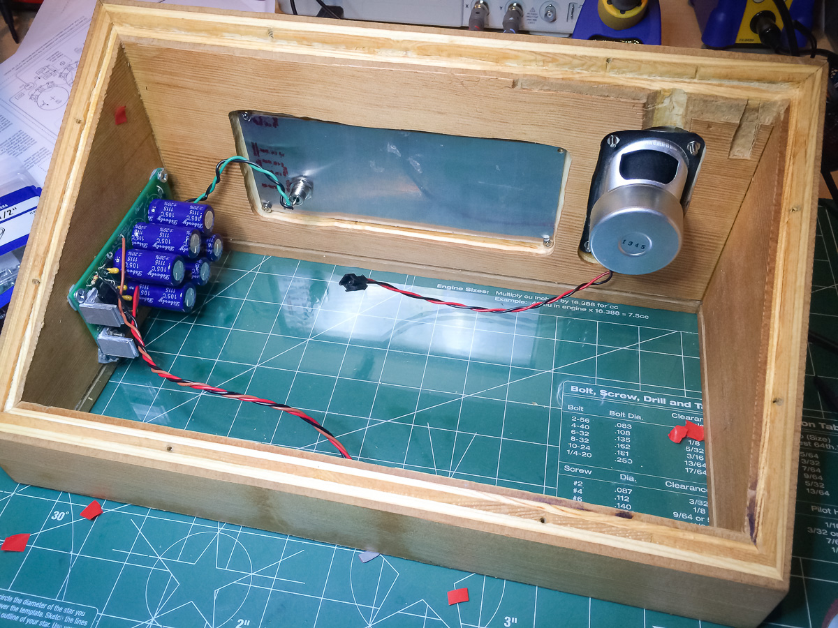
Connected up the power and speaker wires:

And put the front panel in place:
Finally screwed in the metal strips that hold the front panel in place:
The back view:

and the bottom view with the plexiglass base:
Postmortem
[text to follow…]

Hi, there. This project is great. How much did it cost in total for the electronics?
LikeLike
I should figure out how much it costed. During the process I tried not to think about the money. Just to give some idea though: Each potentiometer (with knob) costed $2.54. There are 31 one of them making a grand total of $78.74 … Yikes.
LikeLike
Hey, I am building my own Synth experimenter however I am facing a lot of trouble with the filters. My resonance seems to be working fine but I can’t seem to adjust the Cut-Off frequency of the filter. Even after breadboarding the filter the same problem persists.
Now I noticed in the troubleshooting section you mentioned cranking the trim pot on the VCA. But there isn’t a trim pot on the board’s VCA. Perhaps you meant VCF?
LikeLike
Yes you are correct. I’ll fix the mistake right away. Thank you for pointing that out.
Double and triple check your circuit and resistor values but I remember being surprised how extreme the trim pot had to be adjusted.
Good luck with the project. It’s a lot of work but a lot of fun too.
LikeLike