After the last session I had the following tasks remaining for this new Zumo build:
- Test and configure the encoders and figure out how to get them connected to the mircocontroller.
- Figure out the pin assignments and wire it all up.
- Convert the WallBot V3 code over to the new platform.
The Encoders
First order of business was to ensure the optical wheel encoders were working correctly before securing down the shield.
I jimmied up power for the encoders and motors, attach an oscilloscope and measured their wave forms as the motors turned:
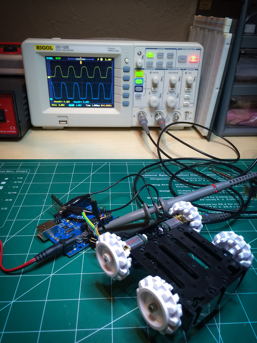
Everything looked like it was working but then one of the encoder channels started giving strange readings. Eventually I discovered the problem; a wire had snapped off at the solder joint.
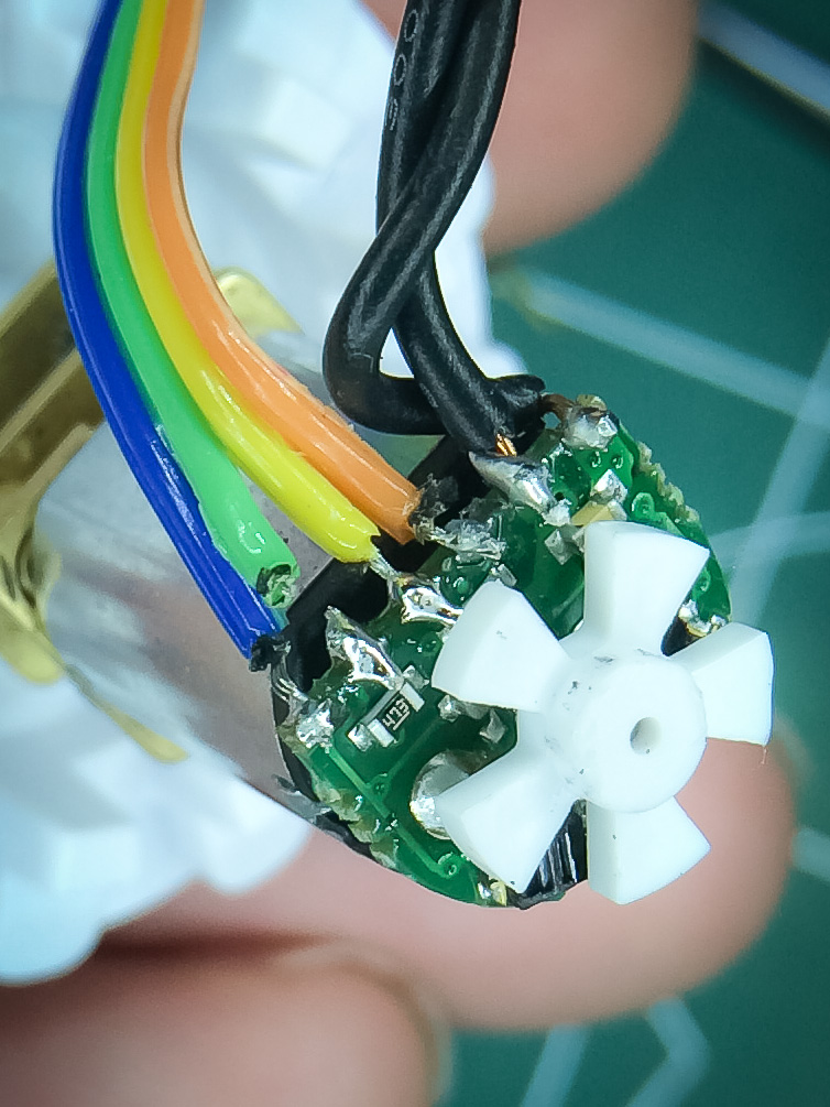
Really bummed. I’m relatively new at soldering and was not looking forward to having to re-soldering this. However, I didn’t have to panic. The desoldering wick worked like a charm and I got back nice clean contacts to work from again.

I believe my mistake with the original work was that I didn’t “tin” the wires first so this time I made sure to do just that. Hopefully these new connections last a long time.
After that I was able to finish testing and configuring the encoders. If you look at the instructions given on the Pololu site they show what the sensor signals should look like with optimal and non-optimal positioning of the encoder wheel. I found that the optimal range for the wheel was quite generous and didn’t require precise positioning. For each encoder I was able to get 4 volts peak on one sensor and just over 3 volts peak on the other.
Here is a screen grab from the oscilloscope:
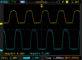
You can see the signals are nicely 90° out of phase and look well formed
It was also suggested that if the signals are strong enough that I might be able to connect them directly to the pins of the microcontroller and by-pass the need for a comparator circuit. Definitely going to get that a try first.
Pins and Wiring
My next task was to figure out how to wire everything to the Arduino… assuming there were enough pins free.
These are the devices I want to add and the number of pins they need:
- Left encoder – signal A and signal B (2)
- Right encoder – signal A and signal B (2)
- Servo – PWM (1)
- Sonic Sensor – trigger and echo (2)
- Bluetooth – Rx and Tx (2)
A total of 9 pins required and one of them needs to support PWM.
The Zumo shield, with the reflectance sensor array attached, uses the following pins
- Reflectance sensor array – assigned to A0, A2, A3, 4, 5 and 11 (6)
- Right motor – assigned to 7 and 9 (2)
- Left motor – assigned to 8 and 10 (2)
- Compass – Uses I2C – A4 and A5
- Push Botton – assigned to 12 (1)
- Yellow LED – assigned to 13 (1)
Which only leaves 6 pins free (I want to use the push button, LED and compass features).
I could drop the sensor array but luckily its design has been really well thought out. Each sensor has a trace that can be cut to isolate the sensor from its assigned pin. You can solder in headers so you can reconnect them again using jumpers, which is what I did:
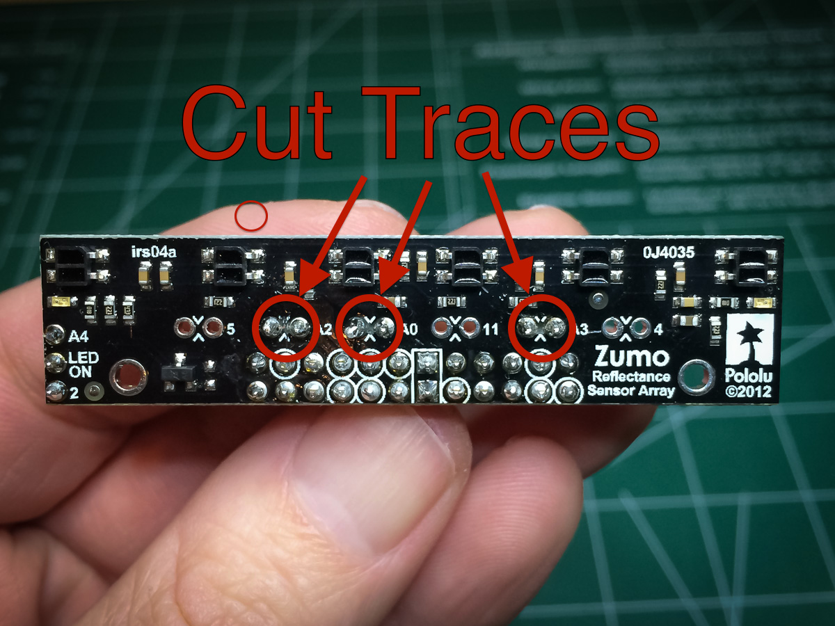
Cut sensor traces for A0, A2 and A3
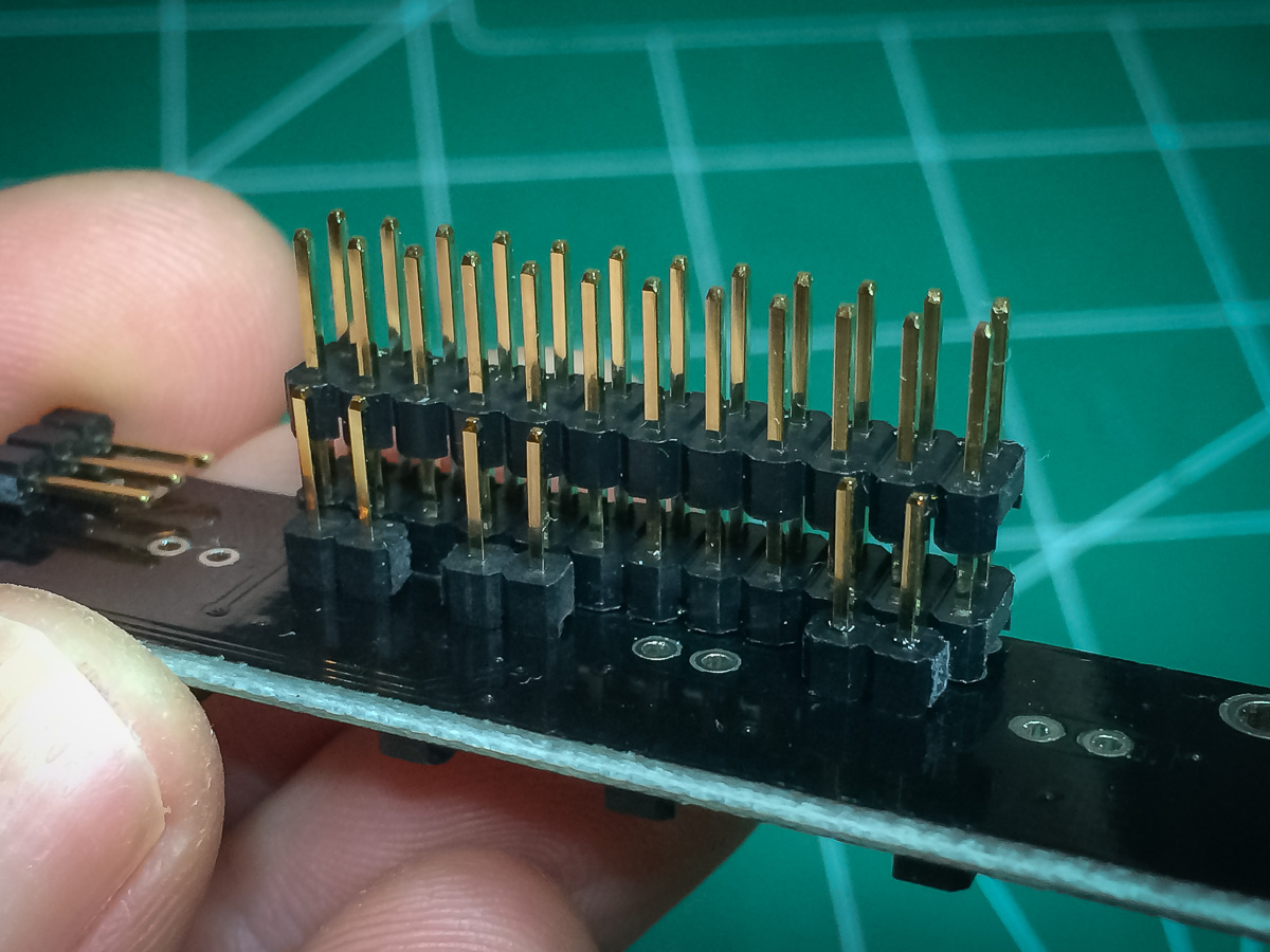
Added headers for cut traces
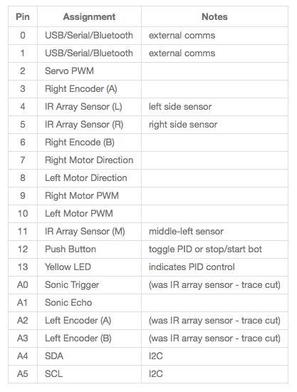
After that I had enough free pins to proceed. The final assignment looks like this:
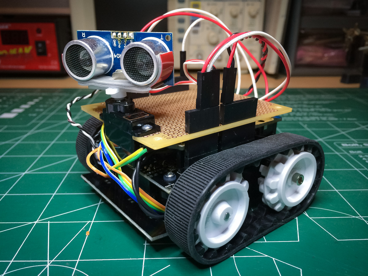
One remaining problem was getting power to each device. Located on the front of the bot are the encoders and sonic sensor. I simply tapped into the 5V and GND pins in the front expansion area with a 1-to-3 power connector.

This ended up being a very neat solution.
As I didn’t want to trim the servo lead (yet) I threaded it through the underside of the perfboard and wired it up from the rear of the bot, using the Arduino’s Vin for power.

I threaded the encoder signal wires through the rear as well. At some point, if the bot works out, I’ll figure a way to minimize the wiring further. Nevertheless, it’s definitely less wiry than version 3 as is.
The Code
Finally I get to the software. I started by taking the version 3 code and modified it to work for the new platform. The only major code change was for the motors… but more on that later.
The Encoders
Again the first task was to see if using the raw analog encoders signals would work.
Using a conditional compile that outputs just encoder information I simply turned the wheels by hand and watched the data stream by. This is what I saw:

Not terrible but there are errors. The errors are either from a bad signal or under-sampling of the signal.
The code is sampling the encoder signals a 1000 times a second. That’s the rate I had for the old encoders that had 48 ticks per revolution. These new encoders have 1200 ticks per revolution. I decided to up the sampling rate by 16 to 16 KHz.
The result:

No errors!
The theoretical tick rate, at max speed of 320 RPM, is 6.4 KHz so we should be sampling at least four times that rate, which would be 25.6 KHz. Still, 16 KHz gets us comfortably to %60 of full power, if not more, and if we are traveling near full power then dead reckoning is not something we’d be too concerned about.
I’m blown away by the resolution of these encoders. It’s crazy. Way more precision than is needed.
Also very happy about the encoders not requiring additional circuitry. The bright spot in the evening.
The Motors
It was all plain sailing till I tried to get the motors turning…. Turns out to be somewhat of a catch-22.
Each motor has two pins: One to set the direction and the other to set the power level. The power level is controlled using a PWM signal. You can set the power level simply by using analogWrite():
analogWrite( motorPin, 127 ); // set motor power to 50%
Problem is the motor PWM control pins are pins 9 and 10 and cannot be used by analogWrite() if the Servo lib is being used… which I am using for the servo at the front of the bot.
Pololu provide their own library for controlling the motors but it uses Timer2 to create the PWM signals…. and I’m using Timer2’s interrupt to handle the encoder sampling.
Pololu provide their own library but it uses Timer1, as does the Servo lib, so that does not help.
My immediate web search doesn’t turn up any quick solutions. I guess I could write my own PWM code and drive it off the Timer2 interrupt…. assuming digitalWrite() is lightweight enough.
So close yet so far…
There is probably some simple answer to this but it eludes me at present.
Read: Zumo – Part IV
Follow-Up
One of the options I didn’t try to do was use Pololu’s encoder library that uses pin interrupts to capture the state changes of the encoders. This would free up Timer1 for the Zumo motor lib and I could use Timer2 to drive the servo. Using the interrupts would also make the encoders less CPU intensive, which is a problem I am having with such a high frequency timer interrupt.
I’ll post here again about how that approach turns out….

Thanks for publishing all the steps of you project! I have solved the wheel encoder with a different approach (I2C D/A converter with Op-Amp): this allows me to produce a clean quadrature signal which can be processed by my microcontroller at full speed 🙂
It is documented here:
LikeLike