Now that the Zumo bot encoders and motors are in working order it’s time to tune the PID controller for driving in straight lines.
Testing the Encoders
Need to first ensure the encoders are accurate by measuring how many ticks each wheel reports when turned 10 revolutions. Theoretically they should show 12000 ticks each.
Let’s see:
Getting counts of around 12035 to 12045 ticks which means each revolution is about 1204 ticks, give or take one. The left and right wheels also seem very close to each other, to at least 1 or 2 ticks per revolution. I think we can safely say the encoders are functioning as well as can be expected.
No PID Control
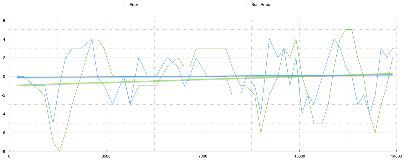
With out any PID correction the bot has a severe drift to the left, as this video demonstrates:
The new Bluetooth module makes collecting realtime data from the bot a cinch.
With the data I made a graph of the error between left and right wheels, i.e. the difference in their tick count (which should be zero for a straight line), as well as the total sum of errors over time. The x-axis is in milliseconds.

Clearly there is an imbalance.
The PID Controller
Time to turn on the PID controller and tuned it to get the errors way down.
For reference here is the code:
//----------------------------------------
// Config
//----------------------------------------

#define Kp            300L
#define Ki            600L
#define Kd            0L

//----------------------------------------
// Data
//----------------------------------------

int16_t pid_lastErr;
int16_t pid_sumErrs;
uint16_t pid_time;

//----------------------------------------
//
//----------------------------------------

void resetPID()
{
  pid_lastErr = 0;
  pid_sumErrs = 0;
  adjustLMotor = adjustRMotor = 0;
  updateMotors();
  clear_ticks();
  pid_time = 0;
}

//----------------------------------------
//
//----------------------------------------

void driveStraight()
{
  static int16_t lticks = 0, rticks = 0;
  static uint16_t ms = 0;
  int16_t dlticks, drticks, diff;
  int32_t delta;
  uint16_t dms;

  get_ticks_since_last( &dlticks, &drticks, &dms);

  lticks += dlticks;
  rticks += drticks;
  ms += dms;
  pid_time += dms;

  if ( ms >= 100 )
  {
    // we assume wheels are turning in the same direction
    int16_t dir = ( lticks < 0 || rticks < 0) ? -1 : 1;

    // make the values positive
    lticks *= dir;
    rticks *= dir;

    diff = ((lticks  - rticks)*100L)/ms + SYSTEM_BIAS;

    // we want the difference to be 0

    // track the integral
    pid_sumErrs += diff;

    // get the differential
    delta = (int32_t) (diff - pid_lastErr);

    int16_t P = (int16_t) ((Kp*((int32_t)diff)
                          + Ki*((int32_t)pid_sumErrs)
                          + (Kd*delta))/1000L);

    pid_lastErr = diff;

    // a positive error means the left motor is
    // turning more than the right so adjust
    // each motor accordingly
    int16_t adjust = (P/2)*dir;

    adjustLMotor -= adjust;
    adjustRMotor += adjust;
    updateMotors();

    lticks = 0;
    rticks = 0;
    ms = 0;
  }
}
And the data is perfect:

It looks a mess but the reality is the error never gets above 9 ticks at any time. That’s a maximum difference of 0.75% between left and right tracks.
However this synchronicity did not result in straight driving.
I’ve scratched my head a lot over this. Had the same kind of problem with the last bot. However, in this case, the drift from center line is consistent run after run, indicating there is some inherent bias in the system. Probably an alignment issue I’m guessing, but whatever it is, it’s consistent.
We could counter this drift by scaling up the right wheel’s tick count. This in effect would cause the PID controller favor the left motor with more power.
And adding the biasing code worked out really well. Ended up using a compensation on the right motor of 1.85%.
This is the code modification:
:
#define SYSTEM_BIAS   -185L      // 1.85%
:
:
    int16_t bias = (rticks*SYSTEM_BIAS)/10000L;
    diff = ((lticks  - rticks + bias )*100L)/ms;
:
:
And this was the result:
And the data:
Probably not the end of the story but a good result so far.

did you use the millis() function for your ms value? At the moment i m using encoders in my project and because the millis() function relies on interrupts on arduinio it wont work as the encoders are relying on the interrupts.
LikeLike
It depends on how the encoders are handled. I’ve used both pin interrupts (recommended) and polling interrupts.
In the case of the pin interrupts I do use mills() for timing. In the cae of polling interrupts I just have the interrupt increment a counter and use that for timing.
You can see the different implementations here:
polling: https://github.com/solderspot/WallieBot/blob/master/WallBot_v4/Arduino/Encoder.ino
pins: https://github.com/solderspot/WallieBot/blob/master/WallBot_v5/Encoder.ino
LikeLike
I should add that for the polling method I used Timer 2 so I could have still used mills().
LikeLike
my apoligies, i think its only with an ISR is running that you cant use delay or millis.
LikeLike
I believe mills() uses timer 0 so if you use timer 0’s interrupt for something else then mills() will be broken.
LikeLike
Hi again, thank you for the response. I have been trying to get the motors on my robot straight for the past few days and i keep running into the same problems where the robot zig zags left to right or the pwm values shoot up making the robot go at full speed. I was wondering are these issues that you encountered. Because the pwm values for the motors increments and decrements so quickly the motors dont respond at the same rate so compensating for error between the encoders overshoots which results in frantic left to right movement. From your code is it that you’re using 200 ms for each time the error in ticks is compensated? How did you get this value?
LikeLike
Yes, I had all those problems.
The first problem you are facing is tuning the PID controller. The update frequency is important. While you want the controller to be responsive you have to factor in the responsiveness of the motor controls too. There is going to be some amount of delay between when you give the motor a command (update) and and when that speed change will actually happen.
The other issue is the resolution of your encoders. If you have small resolution, like 10 ticks a revolution, then you’ll want to reduce your update frequency too.
But the main thing is picking the correct PID values. Start by only setting the P value and adjusting it till you get a reasonable response. Not too high that it over reacts and not too low that it reacts too slowly. Then start adjusting I to reduce the accumulative error.
I recommend graphing the results too. Much easier to see what is going on.
The other problem you are going to face are the systematic errors error of your bot. That is effectively what I was doing with the bias adjustment. However, its more complicated than that. You’ll want to read this post https://solderspot.wordpress.com/2014/05/08/navbot-error-correction-using-umbmark/
LikeLike
Thank you for the response, I fiqured out what i was doing wrong. When i was comparing left and right ticks i was comparing them from when they started. But instead i used a timer to sample the rate of change every 200ms. eg currentLtick – prevLtick . So this gives you a fixed value to compare against another fixed value as opposed to comparing 2 values that are constantly changing. Another thing i was doing wrong was when i was scaling the error i was using the unscaled error as the integral. After this i was able to get the robot moving in a relatively straight line and obviously with more tweaking of the PID constants i can hopfully optimise this. Thank you very much, i think your blog on this topic is really impressive.
LikeLike
I’ve been scratching my head over a similar problem on a little rover I’m working on. Am totally bookmarking this (and that umbmark link) and coming back to it tomorrow. THANK YOU.
LikeLike