
My two previous NavBots both had fundamental issues with regard to dead reckoning. The Zumo’s tracks introduced too much error due to their large surface area and Wallie Bot’s wheel encoders just didn’t have enough resolution for the job.
I decided to build a new bot that addresses those problems. It uses the same chassis and geared motors that Wallie has but also uses the high resolution optical encoders and smaller thinner wheels.
The Build

Parts used:
- 1 x Arduino Uno Rev 3
- 2 x Pololu 5″ Robot Chassis RRC04A Transparent Gray
- 2 x 75:1 Micro Metal Gearmotor HP with Extended Motor Shaft
- 2 x Optical Encoder for Micro Metal Gearmotors 5V
- 1 x Adafruit Motor/Stepper/Servo Shield for Arduino v2 Kit
- 6 x Aluminum Standoff: 1-1/4″ Length, 2-56 Thread
- 6 x Aluminum Standoff: 1/2″ Length, 2-56 Thread
- 6 x Machine Hex Nut: #2-56
- 4 x Machine Screw: M3
- 1 x Pololu Ball Caster with 3/8″ Metal Ball
- 2 x Pololu Wheel 32x7mm- Black
- 2 x Pololu Micro Metal Gearmotor Bracket Extended
- 2 x Pololu Micro Metal Gearmotor Bracket – Black
- 1 x 4-AA Battery Holder, Back-to-Back
- 1 x MakerShield
- 1 x Bluetooth Module
For this build I decided to run the motor/encoder wires down through the chassis so that I could encase the optical encoders using the extended brackets and some black electrical tape. Keep in mind that this design was driven by the parts I happened to have at hand rather than any grand plan.
[UPDATE: Pololu now have magnetic shaft encoders that much easier to setup and use: Magnetic Encoder Pair Kit for Micro Metal Gearmotors]
First step was to solder on the encoders. Here is an image from a previous build:

Next was to mount the motors on to the chassis and marked where to drill to make a hole for the motor wires to come through.


Once that was done it was a simple case of soldering on the wires and mounting the motors once again while routing the wiring through the holes.
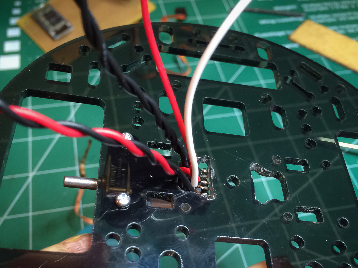
After mounting and testing that the encoders where working I filled in the under holes with hot glue to both provide support for the connections and to stop dust and debris from getting into the encoders.

A little bit of electrical tape is used to cover up the center hole of the chassis.
Using the extended brackets as enclosures for the encoders I initially only used a piece of electrical tape over each end in order to isolate the encoders from one another but it was also necessary to line the enclosure to minimize internal reflections due to the white plastic.
Here you can see the two extended brackets bolted into place using custom drilled holes.

After retesting that the encoders where still working and aligning the wheels as best I could, I used hot glue around the base of the brackets to ensure no dust or debris can get in.
Then it was a simple matter of wiring everything up.
Not the prettiest looking bot but perfect for my needs.
So how does the new bot perform? That is for a future post or two. I will say that it is a vast improvement over the Zumo bot. I am still trying to figure out calibration issues and some strange systematic error behavior.
But to give some idea of performance here is a picture of one of the tests I perform:

Here I taped a sheet of graph paper to the floor and used a black spot as the stating point for the bot. It then traversed a 60cm sided square clockwise and then counter clockwise to end back at the stating point. I then marked on the paper the actually end position. Each grid on the page is about 6mm or 1/4″.
One of the curious aspects was that the clockwise run was always very close to the starting point as you can see from this video of the first run:
Obviously the bot is well calibrated for clockwise travel but not so well for counter clockwise… but that is for another post.

Thanks for sharing! How did you read the encoder signals? Just reading in the analog values, or did you create proper quadrature encoder values from it?
LikeLike
Hi Erich,
I did the same direct connect of the analog signals to the digital inputs. So far it has worked well for this config. However, at some point I intend to build a true NavBot from scratch and if I use the optical encoders I’ll definitely put in the proper circuitry.
LikeLike
Awesome blog. I’ve been trying to think of a way to secure those wires on the encoders for a while now. I’ve already had two get pulled off taking the metal contact along with them while messing around with some test setups.
LikeLike
I v been using a differential drive robot that relies on a basic way for turning based on odometry from the encoders. I want to stop the robot at a chosen angle more accurately than i have been doing. Basically i say something like
if(theta_angle >= 30)
{
stop();
}
for stopping at 30 degrees. The problem with this is the angle almost always has to be greater than 30 before stopping. Meaning the robot may stop at 35-40 degrees. I was reading your code on nav bot and its a lot more sophisticated than mine. I wasnt able to understand how you implemented turnBy() and moveBy() functions. Did you come across this problem of stopping at an exact angle and if so how did you solve it?
LikeLike
Sorry for the late reply… been very distracted by life lately.
Yes this is a very complex problem to solve and is limited by the precision of the devices and the degree of control one has. For example, if you need to be very precise about the angles then you really need to be using step motors and not plain old DC motors. You also have to factor in “latencies” in the system and its physical inertia too. All these things add up.
In my code, which is very crude indeed, I track the “rate of change” of the turns and try to anticipate when I’m about to reach the final angle and give the stop command a little before that. However, in my use case I don’t really care if the final angle is off (hence the crudeness of the code) as I keep track of where the robot is meant to be, as well as where it currently is, and keep adjusting the path to correct for the differences.
What I’ve learnt from doing all this is just how complex and difficult autonomous navigation is (without some kind of fixed external reference). In future I think I will look into using off-the-shelf solutions, like IMUs and such.
LikeLike