The NavBot’s Pilot uses three PID controllers for managing motor control.
The default coefficients for the three controllers are set in the Pilot’s constructor:
//----------------------------------------
//
//----------------------------------------

Pilot::Pilot()
:
:
{
   :
   :
	SetHeadingPID( 5.0f, 0.1f, 0.0f );
	SetSpeedPID( 0.5f, 0.0f, 0.0f );
	SetWheelPID( 2.0f, 1.0f, 1.0f );
   :
   :
}
The current PID settings should work for most setups. However, if you find that your bot is acting erratically then you should perform the following tests to ensure the controllers are tuned correctly for your bot.
[I’ll try to update this post with actual examples of how problems with the PID controllers might affect the operation of the bot.]
Test the Wheel PID Controller
This controller works to ensure that the both wheels rotate evenly during turns. This minimizes lateral movement while turning in place.
To test the controller, in NavBot_v1.ino set CFG_CALIBRATE_TURNS to 1 and CAL_TURNS to 4. Set all the other CFG_XXX options to 0:
//----------------------------------------
// Config Logic
//----------------------------------------

#define CFG_TEST_ENCODERS     0     // print encoder ticks
#define CFG_TEST_MOTORS       0     // verify motor wiring
#define CFG_SQUARE_TEST       0
#define CFG_CALIBRATE_MOVE    0     // straight line movement
#define CFG_CALIBRATE_TURNS   1     // turning only test

#define CAL_DISTANCE      2      // meters to move
#define CAL_TURNS         4     // num of turns (+ right, - left)
In Pilot.h set PLT_GRAPH_WHEEL_PID and PLT_SHOW_ERRORS to 1 and all others to 0
#define PLT_DEBUG_STATE             0
#define PLT_DEBUG_TASK              0
#define PLT_DEBUG_ENCODER           0
#define PLT_SHOW_ERRORS             1
#define PLT_MOVE_INFO               0
#define PLT_TURN_INFO               0
#define PLT_SPEED_INFO              0
#define PLT_SHOW_HEADING_ADJUST     0
#define PLT_SHOW_TURN_ADJUST        0
#define PLT_GRAPH_WHEEL_PID         1
#define PLT_GRAPH_SPEED_PID         0
#define PLT_GRAPH_HEADING_PID       0
Compile and download the code. Open the serial monitor. Hold the bot off the ground and press the start button. The bot should perform four full clockwise turns and the values of the Wheel PID controller should be displayed in the serial output so:

The four printed values are time, err, sum and output. time is in milliseconds, err and sum are in millimeters. output is the motor level adjustment for left and right wheels.
If you see encoder errors throughout the run then make sure to go debug and fix the encoders.
err is the difference of travel between the right and left wheels since the last update. sum is the sum of all the errors. The PID controller tries to keep the error at zero. You want to look over the output and see that err and sum are kept very low.
You can also take the serial output and import it into a spreadsheet to generate a graph of the results:
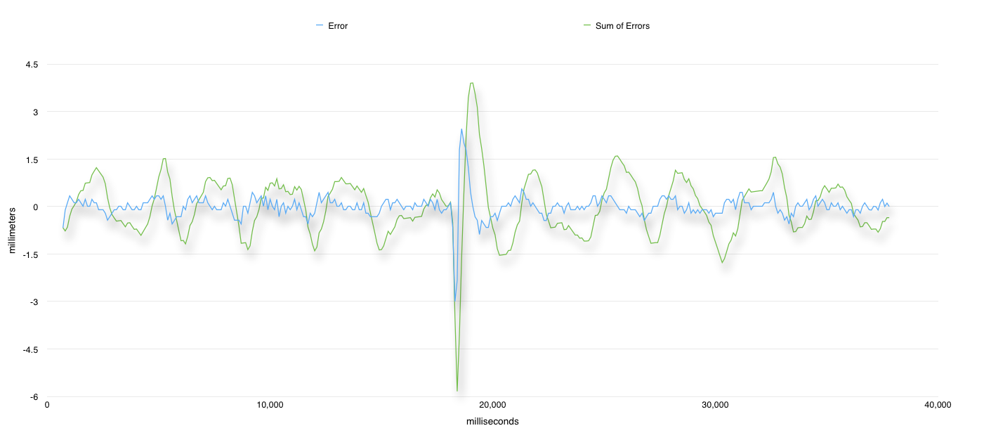
This lets you visualize how the PID controller is functioning. In the above example (for my BlackBot) the err never gets more than 0.5 mm and the sum not more that 2 mm. There is a spike in the middle of the run where I interfered with the turn by using a finger to slow one of the wheels. You can see that the PID controller quickly corrects and the error goes back to sub 0.5 mm.
Your output might look very different depending on the resolution of your encoders. BlackBot has 900 ticks per revolution for a 32mm diameter wheel so it’s encoder resolution is about a tenth of a millimeter.
Test the Speed PID Controller
Pilot uses a PID controller to regulate the overall speed of the motors for both turning and for moving forward.
[Technically there should be two controllers; one for turning (degrees/sec) and one for movement (mm/sec). For now it seems that one controller works for both but this may change in the future.]
Perform the same procedure as we did for the Wheel PID controller above but this time set PLT_GRAPH_SPEED_PID to 1 and all others to 0
#define PLT_DEBUG_STATE             0
#define PLT_DEBUG_TASK              0
#define PLT_DEBUG_ENCODER           0
#define PLT_SHOW_ERRORS             1
#define PLT_MOVE_INFO               0
#define PLT_TURN_INFO               0
#define PLT_SPEED_INFO              0
#define PLT_SHOW_HEADING_ADJUST     0
#define PLT_SHOW_TURN_ADJUST        0
#define PLT_GRAPH_WHEEL_PID         0
#define PLT_GRAPH_SPEED_PID         1
#define PLT_GRAPH_HEADING_PID       0
For the speed controller we are not concerned with the sum of errors so we just need to look at err values.
This is what BlackBot’s turning data looks like:

err is the difference between the target speed and the current speed. It is curious that there are sudden jumps in err. Not sure why that is. It might have something to do with how the Navigator updates at a much higher frequency (100Hz) from the Pilot (10Hz).
We do the same test for movement by setting CFG_CALIBRATE_MOVE to 1 and CAL_DISTANCE to 2
//----------------------------------------
// Config Logic
//----------------------------------------

#define CFG_TEST_ENCODERS     0     // print encoder ticks
#define CFG_TEST_MOTORS       0     // verify motor wiring
#define CFG_SQUARE_TEST       0
#define CFG_CALIBRATE_MOVE    1     // straight line movement
#define CFG_CALIBRATE_TURNS   0     // turning only test

#define CAL_DISTANCE          2      // meters to move
#define CAL_TURNS             4     // num turns (+ right, - left)
Here is BlackBot’s speed controller data for movement:

Test the Heading PID Controller
The final PID controller is used to correct for heading errors while the robot is moving to a waypoint.
This time we set PLT_GRAPH_HEADING_PID to 1 and all others to 0
#define PLT_DEBUG_STATE             0
#define PLT_DEBUG_TASK              0
#define PLT_DEBUG_ENCODER           0
#define PLT_SHOW_ERRORS             1
#define PLT_MOVE_INFO               0
#define PLT_TURN_INFO               0
#define PLT_SPEED_INFO              0
#define PLT_SHOW_HEADING_ADJUST     0
#define PLT_SHOW_TURN_ADJUST        0
#define PLT_GRAPH_WHEEL_PID         0
#define PLT_GRAPH_SPEED_PID         1
#define PLT_GRAPH_HEADING_PID       0
Again we do not care about the sum of errors. We just care that err is kept small and close to zero:

Tuning the Controllers
If any of the controllers are not maintaining small error values, or they are causing the errors to increase, you will need to adjust the coefficients to correct for the problem.
Unfortunately choosing the optimal values is mainly a trial and error process. It’s usually recommended to set the I and D values to zero and first find a value for P that manages to reduce the error value quickly but with minimal oscilation about zero. Once you have a suitable value for D then modify I and D to see if you can get better results.
To modify the values, for example for the Wheel Controller, call the Pilot’s SetWheelPID() method from the init_bot() function:
//----------------------------------------
//
//----------------------------------------

void init_bot()
{
    // do all bot initialization here
   :
   :
   pilot.SetWheelPID( 2.0f, 0.0f, 0.0f );
   :
}
Where the first parameter is the P, second is I and third is D.
Feedback
If you are have problems with the PID controllers please let me know. I am thinking that the current values should work for all robots as all the inputs to the controllers are normalized. However they very well may need to be tweaked to handle more extreme input ranges.
